
Agilent 2000a / 3000a Oscilloscope NAND Recovery
[06.04.24]

I ran across an oscilloscope in need of love and attention on the Internet's favorite online auction site. After some back and forth from the seller, I found out that the scope didn't boot, one of the tell tale problems of the Agilent 2000a / 3000a / 4000a X-series oscilloscope series. The no boot condition can be caused by one of three things: a failed power supply, the mischievous NAND corruption error, or both. The seller took my lowball offer of $220 and just like that I had another project in my life.

On initial opening, the scope looked like it had road rash. Every single knob and edge of the plastic shell had distinct pavement scuff marks. There were some cracks in the front plastic bezel and rear molded fan grill, further confirming that this scope was dropped multiple times. The horizontal adjust encoder was also bent and two knobs were missing.


Not the end of the world, let's double check the description. I plugged it in and the scope powered up with 3 of the 4 indicator lights. Ref, Math, Digital and were illuminated, nothing on serial. The scope stays perpetually in this state with nothing displayed on the LCD. Button presses yield no response. The continuously-on fan and 3 indicator lights are the only source of life. Using a special sequence of power button + unlock cal switch displays no lights on the instrument. The seller clearly did not test the instrument.

I covered the infamous power supply failure in my colorful youtube repair video of a 350mhz DSOx3034 oscilloscope, embedded below. The problem boils down to a poor implementation of an inexpensive power supply, where the primary side is left on indefinitely when the oscilloscope on/off switch is in the off state. This leads to thermal runaway of components and eventual catastrophic failure many years down the line. That's clearly not the problem with this unit.
Disassembly
Realizing that this was going to be an involved repair, I decided to take care of the obvious housekeeping first. I did not want the busted encoder serving as a pressed / intermittent input during future software troubleshooting and I actually had a few spare Agilent knobs lying around. Let the disassembly commence.

The rear shell of the oscilloscope is removed first. There are (4) T20 torx screws that follow the perimeter of the instrument. Yes, the 4th is hidden inside the spare probe compartment.

Following, the plastic front panel is unclipped from the sides, taking extra care not to tear the ~30 pin flat flex cable. There are ~6 clips around the perimeter of the instrument that you have to methodically pry away from the aluminum mid frame of the oscilloscope.

The front panel PCB is sandwiched between the plastic front panel injection and the front rubber over-molded knobs. It's quite a clever assembly and cost effective assembly. To remove the front panel PCB, first remove all 15 over molded nobs. Pull firmly on base of the knob or use a plastic spudger, the knobs will come off easily. Headed toward the back side of the front panel, depress the 8 molded-in clips and slowly jimmy the board out of place. Don't forget to carefully remove the 10 pin flat flex cable that connects to the menu buttons under the LCD. Look ma, no screws!

Finally, the front control PCB is free for analysis. The PCB is relatively straight forward: It's an input board with a bunch of mechanical encoders and plated pads for carbon-backed silicone domed keys. I can safely conclude mechanical encoders because of size, cost and build quality. Optical encoders are hard to miniaturize and will consume a product's BOM in short notice - especially if you need 15 control knobs!
Encoders
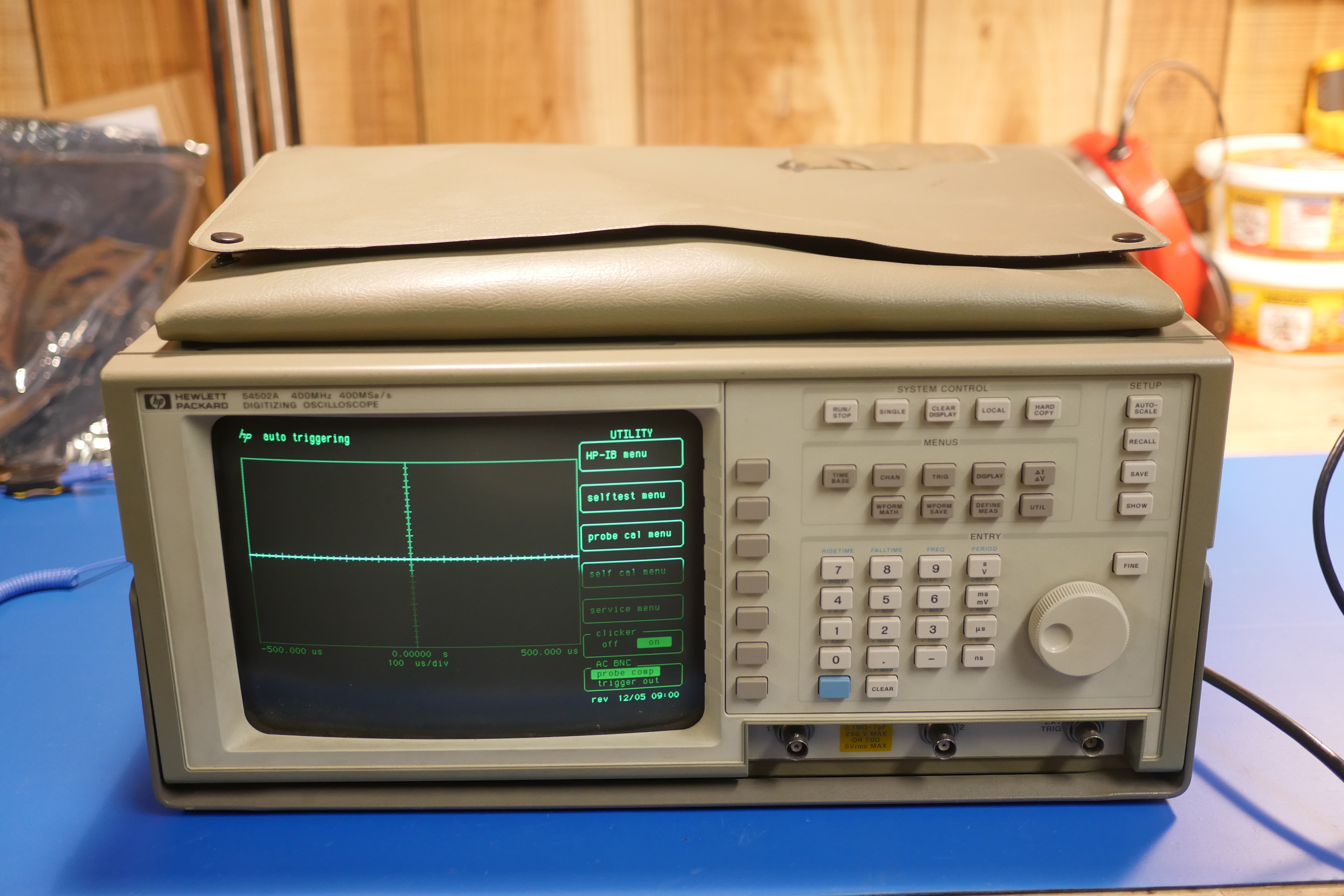
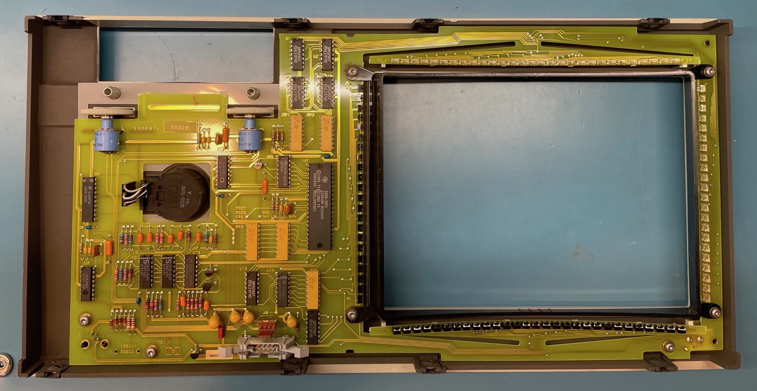
HP tried doing this in the early 90s with the 54500 series oscilloscopes. There was one main control knob and buttons to select each mode. That one knob was of course, an optical encoder. HP tried to make this affordable and produced it in house, leading to HP's own line of optical encoders which was later separated from the company and rolled into Agilent. The semiconductor products group of Agilent was later spun off into Avago technologies. Avago then purchased Broadcom and assumed the Broadcom name. More importantly, the optical encoders still live on today! The HP 5000 series must not have sold well or the interface must have annoyed engineers thus more knobs became the status quo.


You can really seen the carnage on the encoder shaft - nice and straight. The good news is that only one mechanical encoder was damaged, not two and there were zero signs of PCB damage. What a score! With a macro lens, I was able to read a very faint screen printed "24k4J" on the broken encoder. This string yields zero useful information from an online search, but 24 is a useful number.


Twenty four could be indicating the resolution of the encoder, the number of detents or some kind of internal part series. The damaged encoder is smooth, so 24 is not for detents. The detented encoders on the scope were counted as 24 detents, but the broken device under test is a non-detented encoder. What about resolution? Sure we could assume 24 pulses per 360 degree revolution, but can we do better? Why yes! An easy way to test the number of pulses is to implement a recommended encoder circuit, place an oscilloscope probe on Terminal A and Terminal B and ground each probe. You will need an oscilloscope, passive probes, a 5v power supply, some 10k resistors, 10nf capacitors and a breadboard. I used my lab power supply, but any 5v wall wart would be fine.


The encoder is an input device, thus it will not output anything over channel a or b until physically turned. Put the oscilloscope in single shot mode and slowly turn the knob. Once the knob is turned, two square waves should be displayed, one on ch1 and the other on ch2 of your oscilloscope. The square waves will be shifted slightly between channel 1 and 2. When the rotational direction of the encoder is changed, the channel with the leading edge square wave will become the lagging square wave. Taking this into account, mark a physical start point (say with sharpie) on the encoder, put the oscilloscope in single shot mode and rotate the encoder. The oscilloscope will capture a waveform whenever the input to either ch1 or ch2 changes. Continue incrementing this procedure to count the number of times the oscilloscope captures a waveform. This number is your pulses / revolution. Looking back, this test would have been easier and more reliable if I removed a non-damaged non-detented encoder from the oscilloscope. The broken one was finicky and yielded inconsistent results (26 pulses the first time). The broken encoder was indeed 24 pulses/rev.


A quick digikey search later and I found the mechanical encoders used in the 2000/3000/4000/6000 x-series oscilloscopes. Enter the Bourns PEC12R series. The PEC12R features the same PCB layout, mechanical dimensions and specifications to match the ones used in the oscilloscope. These are 30k rotational cycle life mechanical encoders with 20k button cycle life offered in detented and non-detented versions along with different resolution options. Oddly enough, this information became priceless for my fume extractor project. I overestimated the encoder lifetime needed for a user interface by a long shot. What can I say, a good knob can make or break a product :D.
Agilent / Keysight Course Adjust Knob (detented): Bourns PEC12R-4220F-S0024
Agilent / Keysight Fine Adjust Knob (no detents): Bourns PEC12R-4020F-S0024


The encoders arrived quickly but were very vague. I find it a bit underhanded that Bourns took the lazy train. No signs of manufacturer branding, detent number, resolution part number or series. Shame, shame!


While inside the scope, I decided to deal with the litany of cracks in the front and rear plastic panels. Plastic cracks are an easy fix with fancy epoxy or a simple soldering iron. The main downside to plastic welding is the uneven surface finish left behind. I opted to plastic weld the broken seams from the inside since my good epoxy ran out and no one else will ever see the inside of the scope. NOTE: plastic welding creates bad fumes. Do this outside with a mask or in good ventilation. Melting ABS + PVC plastic blends will yield chlorine gas. ABS + PVC is not common anymore, but still good to know. In a rather surprising discovery, a white eraser and some elbow grease transformed the scope back to it's original OEM state. Who would have guessed!
Digging In
With the cosmetics out of the way, lets dig into the heart of the problem. As stated above, the oscilloscope switches on, powers the fan, illuminates some lights but stops short of displaying anything on the display. Comparing it to videos of other 2000a / 3000a oscilloscopes booting, there's an additional stage of led illumination and button panel self tests that occur before the main LCD displays anything. It's always a good idea to rule out obvious problems, thus thou shall check voltages. Keysight has quite a thorough service guide for troubleshooting and repairing this oscilloscope. Page 78-82 detail the numerous test points to probe and the appropriate voltage ranges. Running low on cycles myself, I checked the power supply for 12v and ruled it out. Based on the current operating conditions, the scope seemed to be hanging on boot. This stuck-on-boot issue has been hammered to death on eevblog.com/forum, with a 130+ page thread dedicated to various repair methods for for the 2000a / 3000a / 4000a scopes. My DSOx-2014a met all the criteria for a scope with boot related issues.


Oscilloscope Boot Up Process
An overview of component enumeration is in order. A C13 115v AC cable is plugged into the scope and feeds the Line Filter Board. The board features both the AC line filtering and the main on/off switch for the scope, but the on/off switch is for the secondary side and not the primary side of the PSU. When the on/off switch is pressed, the ps-on signal is tripped and main 12v switch mode PSU outputs through a 20 pin mini-fit jr cable to the main oscilloscope PCB. This large 12v rail is then converted to the various internal system rails.

The heart of the beast is an ARM microcontroller that runs off the 3.3v rail and handles the memory controller, NAND controller, LCD display menu/interface, windows CE, networking, and interfacing to the FPGA. The FPGA is connected to the arm chip via an EXPI (External Local Bus Interface). FPGAs have many internal power domains and require strict power-up / power-down sequences for the different voltage phases that power the array, oscillators, and I/O peripherals. Voltage rail ramp-up / ramp-down is another important factor for FPGAs and ASICs and certain rails demand low ripple and require an LDO for low noise.


FPGAs are volatile, and require reprogramming every bootup, usually from a QSPI like memory. FPGAs excel at parallelizing data streams and in this case, handles the less critical external measurements, waveform search & navigation features, and math functions relegated from the MegaZoom IV ASIC. The MegaZoom IV ASIC handles the grunt of the signal processing and handles both the analog and digital inputs from the front end of the oscilloscope. The data from the FPGA is shuttled to external memory and accessed by the main micro for final processing.

Here's a component overview of top component side of the main PCB. Beginning from left to right, there is a power stage section in the upper left hand side of the PCB besides two black heatsinks. Under the left most heatsink sits a Quad 8-bit 1G sample/sec ADC (Analog to Digital Converter) for the 4 analog channels alongside the custom Agilent MegaZoom IV SOC ASIC for waveform, acquisition and digital functions. You can visually see snake-like traces that are length matched differential pairs which truncate at the ADC. A Samsung "k4t51163qi-hce6" DDR2 memory chip is found adjacent to the Megazoom IV ASIC. Below the Megazoom IV are the (4) metal-can shielded front end modules for channel 1 --> channel 4. Working toward the center of the PCB, the Xilinx Spartan XC3S500E FPGA and "ST SPEAR600" 32 bit ARM microcontroller take the spotlight with power stages above and below, likely for the specific low voltage power rails required for the Spartan FPGA. Just below the ST arm chip sits a "micron D9lhr" DDR2 memory chip. Moving further right, a familiar 20 pin Molex Minifit-Jr plug for the main 12v power supply. A 3v 2032 primary lithium solder-in battery sits just above the Mini-fit Jr with an arrangement of a USB ports and trigger BNCs besides. The external module port sits just below this arrangement along with the FPC connectors for the front button panel / keyboard and the LCD.

The opposing side of the board is far less populated. The bottom edge features the waveform gen out BNC, the front 40-pin IDE-style connector for the external MSO module, a USB-A port, some probe compensation clips and the (4) physical BNC channels. You'll notice the remainder of the board is chuck full of SMT caps, with plenty decoupling capacitors adorning the underside of the main ASICs and main CPU. Inductors are spread throughout the back size, indicating there are many specific voltage rails needed for the critical components of this design. The official service manual confirms this with a table of 13 different voltage rails!

PCB Annotated by me. Credit: Dave Jones, EEVblog.
The TSOP48 NAND memory package is what we are most interested in. It is located within close proximity to the back side of the main ST SPEAR600-2 microcontroller. This TSOP48 memory package is a 1gbit or ~125mb Micron / Numonyx / ST NAND01gw3b2cn6 NAND package. The windows ce boot partition and the entirety of the oscilloscope operating system are stored here.

2000a TSOP48 NAND package. Credit: Dave Jones, EEVblog
Where to Start?
Having concrete evidence of a boot failure would be nice, and the only way to truly know if there are problems at boot is if you could access a live serial output monitor / terminal / bitstream while the ST Spear600 is loading the initial bootloader. Luckily, this oscilloscope series has been around for some time and the clever folks on the eevblog have poked around and found out the (10) pin 0.1in header near the DDR2 memory of the main ST Spear600 is indeed a UART header.

This header varies in orientation and location between scope mainboards so let's find the pinout another way. With the oscilloscope unplugged, put a multimeter in continuity mode with one probe against the shell / any PCB screw terminal and find which pins on the 10 pin header is GND. Two of the pins should be gnd. This scope is based around an ARM CPU. Arm based chips run on 3.3v, thus 3.3v logic levels. The SPEAr600 datasheet above confirms this. The scope design engineers are awesome and left in plenty of silkscreen labels across the PCB, so find test point VP3V3, the 3.3v rail, and check for continuity with any of the 10 pins. You will find that one pin is indeed 3.3v rail leaving 7 unknown pins.

UART is an Asynchronous communication so only two pins, (Tx) send and (Rx) receive, are needed. Which of the 7 are Tx and Rx? The best way to find out is with a logic analyzer and this excellent guide from River Loop Security. I happen to have an MSO scope on hand, so why not flex some electrons?


Before plugging anything into fancy test equipment, it's a good idea to check the reference manual. Two important bits of info about the 2000a / 3000a MSO capabilities: the MSO adapter can accept low power signals up to 40v, but it offers no input protection when the host oscilloscope is off. Thus, if the DUT (Device Under Test) has a short of some kind near the area of probing, and the host oscilloscope is not powered, there's a good chance you've just damaged the Maxim MAX9201 comparators in the logic analyzer section of your scope! It's worth checking all 10 pins for voltages outside the MSO operational range.

The 0.1in pitch header sure makes connecting the mini clip grabbers on the MSO adapter easy. The MSO adapter can do 16 channels on a 3000a oscilloscope, but we are only interested in exploring 7 pins. Most scope manufacturers suggest connecting a gnd connection for every second probe wire for best results. In this case I'm just going to use the two easily accessible 0.1in header gnd pins for the adapter and one probe. Make sure to not to add or remove clips when the DUT is powered.

Right off the bat, it becomes evident that there is plenty of activity on Data line 3, in this case, the exact same pin referenced in the above eevblog uart pinout diagram. Tx has been found. With the UART hex decode function on, UART packets can be decoded from the noise.


Finding which of the remaining 6 pins is the Rx pin is a bit of a headache and will require trial and error. Traditionally, when two UART devices are talking to each other, the RX pin on one device should be connected to the TX pin on the other and vice versa. This creates an additional headache as not every device follows this convention.

Setting up Comms
UART adapters are plentiful and cheap these days, but the quality and reliability of those found online can vary wildly. I highly suggest grabbing a genuine 3.3v FTDI cable from digikey because they are an actual supplier and not a re-labeler or importer of clonezone product. I went with two UART cables from amazon and regretted it. Double check and make sure you're using a 3.3V serial adapter, not 5V!


Connect Rx, Tx and GND from the scope pinout to the USB to UART adapter. It's best to use some 6-8in long dupont cables (0.1in header extension cables) for this to enable complete oscilloscope reassembly. Page 75 of the 3000a service guide shows the proper operational conditions of a 3000a under test, but it is incredibly fiddly and additional cooling will be needed for continued operation. This reflashing process will take nearly 2 hours to complete. Leaving fancy test equipment improperly cooled for that long is silly.

My go to for legacy hardware communication is to grab an old laptop with dedicated usb 2.0 ports and go to town. I've had issues with 3rd party usb 3.0 hubs. With TeraTerm installed, and the serial port communications adjusted to 115200 baud, I was able to get a U-boot output from the scope on turn on. U-boot only runs for a short amount of time on a working scope and you'll have to hit space very quickly to stop boot. When there's a bootup problem, that's obviously not the case :D.


Digging through that 130+ page eevblog thread, one method of recovery surfaces that is most repeatable, dubbed the "Titiris Method". Below is a revised version of the Titiris Method. Some of the original links have moved or vanished, and I added additional context to make the process more understandable and easier to troubleshoot.
Revised Titiris Method
Connect a UART cable to a computer. Open a connection with TeraTerm. Select COM port, 115200 baud, 8bit data, No parity, 1 bit stop bit and no flow control. TeraTerm includes YMODEM features, putty does not. The connection should look like:
U-Boot 2010.03 (Jan 26 2011 - 12:37:34)Agilent P500

CPU:   SPEAr600
DRAM:  128 MiB
Flash: 512 KiB
NAND:  128 MiB
In:    serial
Out:   serial
Err:   serial
SerNum:serial number not programmed
Chip:  BD Board Rev: 4
Net:   smsc
Press space to stop autoboot:  0
It continues until posting a CRC error or something that aborts your booting process. Screenshot / take note of the length of the data in hex that is attempting to transfer under "Completed files(s)." This value is crucial in helping determine what version of the agilent/keysight firmware is running on your scope. Turn off the scope.
Below is a list of nk.bin firmware internal program size lengths. U-boot looks for a data carrier that contains an nk.bin file that contains the entirety of winCE, which is the main operating system for the 2000a/3000a oscilloscope. Based on the hex value length from your terminal window, acquire the specific firmware version closest to yours in size. Here is my archive of 2000a / 3000a firmware that was downloaded publicly from Keysight's website before the most recent Keysight website redesign nuked them. Start with the firmware value closest to your scope firmware version, but grab the firmware version above and below as a fallback. Hex and Decimal values are missing for certain firmware versions as those are missing from my archive and I cannot verify the lengths. If your length value is between values, you may have to hunt around for an older firmware, ask keysight nicely (they have great support), or ask on the eevblog forums.
Firmware version	Short  Hex          Decimal
01.01.0000000000	1.01
01.01.2010010700	1.01
01.10.2011031600	1.10 - 0x01238818 - 19105816
01.10.2011042700 	1.10
01.20.2011063000	1.20
02.00.2011101301 	2.00
02.01.2011111500 	2.01
02.10.2012022200	2.10 - 0x0124867C - 19170940
02.11.2012040400 	2.11
02.12.2012041800	2.12
02.20.2012110802	2.20 - 0x01248680 - 19170944
02.30.2013032600	2.30 - 0x012F9870 - 19896432
02.30.2013040502	2.30 - 0x01248684 - 19170948
02.31.2013040901	2.31
02.35.2013061800	2.35 - 0x013064D4 - 19948756
02.36.2013091300	2.36 - 0x013064E8 - 19948776
02.37.2014052002	2.37 - 0x0130656C - 19948908
02.38.2014110300	2.38 -
02.39.20151022602	2.39 - 0x013387B8 - 20154296
02.40.20150828001	2.40
02.41.2015102200	2.41 - 0x015264A8 - 22176936
In this case, we will use firmware v2.35 as an example. v2.35 is a .CAB file. Extract nk.bin.comp and infiniiVisionSetup.cab from firmware v2.35 with 7zip. "nk.bin.comp" contains the kernel image and recovering WinCE. "infiniiVisionSetup.cab" contains the oscilloscope application. We want to read the contents of nk.bin.comp to determine the size of the winCE boot image in each version of the agilent firmware and find the one closest in size that matches our present scope. Create a directory that contains the extracted nk.bin.comp, infiniiVisionSetup.cab and all of the extracted files from nkbintools.zip. Run CMD.exe at that folder location. Use bincompress.exe (included in nkbintools.zip) to decompress nk.bin.comp to nk.bin: bincompress /d nk.bin.comp nk.bin. Use viewbin.exe to get the info from nk.bin that we will use later: viewbin nk.bin. Here's the results. under "Image Start = 0x80361000, length = 0x013064D4" length is the value you seek.

The length of mine was 0x1248684 or firmware 02.30.2013040502. I only had firmware 02.30.2013032600 on hand, but it was close enough that it worked! Using the data we got from viewbin.exe, with the same CMD window open, convert the nk.bin into the nk.nb0 (the binary) with cvrtbin.exe which will be uploaded later. cvrtbin.exe -r -a 0x80361000 -w 32 -l 0x013064D4 nk.bin. This will create a nk.nb0 in the same folder. Check it exists and remember the location. Run TeraTerm with the same serial port parameters: 115200 baud, 8, N, 1. Hold your keyboard space bar and turn on the scope. This will interrupt the U-boot bootloader, showing a prompt:
U-Boot 2010.03 (Jan 26 2011 - 12:37:34)Agilent P500
CPU:   SPEAr600
DRAM:  128 MiB
Flash: 512 KiB
NAND:  128 MiB
In:    serial
Out:   serial
Err:   serial
SerNum:serial number not programmed
Chip:  BD Board Rev: 4
Net:   smsc
Press space to stop autoboot:  0
p500>
With the bootloader stopped, let's start the upload process. U-boot Loady function lets you load a binary file over a serial line (ymodem mode). If you are curious for all the loady modes, type p500> help loady. To use Loady, the function will look like: loady [ offset ] [ baud ]. This will load a binary file over a serial line with offset 'off' and baud rate 'baud.' At the prompt, type: p500> loady 0x0361000 115200. Note from FrankBuss: In case you wonder about the 0x80361000 and 0x361000 difference: this is because of physical and virtual memory addresses. Fortunately, the mapping is really easy in this case. The prompt should spit out: ## Ready for binary (ymodem) download to 0x00361000 at 115200 bps...
The "CCCC" will continue until you start to send a file, or a timeout happens after a couple of minutes, maybe. In Tera Term go to File-> Transfer-> YMODEM->Send... and open the nk.nb0 that you have prepared beforehand. This transfer takes about 45 minutes. YMODEM is a fast protocol, but the serial connection is 1000 times slower compared with a 100BaseT.
YMODEM transfer can sometimes fail. Mine failed on me a few times. All of those times, the "total size" in bytes transferred was nowhere near the size from the above table. In my case below, the first nk.nb0 transfer was 1053696 bytes. The second transfer was 6907904 Bytes. It was supposed to be 19170948 bytes. This was likely due to clonezone ftdi uart cables.

I originally used v2.35 firmware (19948756 bytes) which was the wrong size nk.nb0 file and it caused a hang on "starting application at 0x00362000" just as above.

While waiting, prepare a USB flash drive. Use a small USB flash drive formatted in FAT and ideally less than 8gb. 128mb is likely the smallest for comfort. My scope randomly failed and rebooted with a 16gb sandisk usb3.0 extreme card. Avoid USB to SD card adapters.
WinCE CAB Manager 3.0 can extract the files from infiniiVisionSetup.cab, but I was unable to find them. Fortunately, in the nkbintools.zip there is a Python script, dosetup.py, that does the job. The steps are:
- install Python 2.x.x
- Decompress infiniiVisionSetup.cab into an empty folder. you will get many files with scrambled names.
- copy dosetup.py into the same folder
- run python dosetup.py or simply double click on dosetup.py. Python instructions are duplicated in the readme.txt in the .zip
Setting up the USB Flash Drive
Now you have the contents of infiniiVisionSetup.cab exploded in a tree. The next step is to copy this folder and its contents to a USB flash drive. The folder structure is found here but revised below:
\
+-Secure
  +-infiniiVision
	+-fpga
	+-upgrade
	+-web
	  +-css
	  +-help
	  +-image
	  +-include
	  +-web-socket-js
	  +-lib
	  +-Lxi
	    +-Identification
	  +-navbar
+-Startup
infiniivisionStartupOverride.txt
USB folder procedure:
- copy the contents of the Secure folder in your USB root.
- copy the Temp folder in your USB root.
- make a folder name Startup in your USB root.
- create a file inside the folder Startup, named infiniivision.lnk, containing 51#\usb\Secure\infiniiVision\
infiniivisionLauncher.exe - create a file in your USB root, named infiniivision
StartupOverride.txt, containing "True" - copy the stock firmware .cab file form keysight to your USB root. Use 02.40 or above. 2.41.cab is in the above archive.
Return to Tera Term which was transferring the nk.bin. At the end of the transfer, your screen should show this below code right after the last C, without any CR/LF. Check if the bytes received are the same. In the case of v2.35 it should be 0x013064d4.
CCCxyzModem - CRC mode, 1(SOH)/19482(STX)/0(CAN) packets, 5 retries
## Total Size      = 0x013064d4 = 19948756 Bytes
Plug the USB flash drive into the scope front USB port.

The last step: Use the go U-boot command to execute the kernel just downloaded. Cross your fingers, pray, say thanks to James Clerk Maxwell, or whatever your belief recommend, and type at the prompt: p500> go 0x00362000. The terminal should start echoing a long list of messages, starting with...
## Starting application at 0x00362000 ...
Windows CE Kernel for ARM (Thumb Enabled) Built on Jan 24 2013 at 14:52:37
Setting up for a Cold Reboot
Done Setting up for a Cold Reboot
Windows CE Firmware Init
(...)


396 lines after the "go" command, you should see the last line: InfiniiVision is running and your scope is running!
Once your scope is resurrected and boots properly, it is imperative that you update to a bootloader-patched firmware. This firmware contains a self-recovery mode, new NAND drivers and memory access algorithm. Do not “unpack” or “unzip” the stock .cab firmware file. Leave it be. Since your oscilloscope is likely running a pre-2.41 firmware, make sure the file has a .cab extension. Scopes running pre-2.41 firmware cannot read .ksx files. To Install: Place the file on a USB flash drive, plug it into front scope USB. Press [Utility] > File Explorer, select the file, then, press Load File. It will take ~10 minutes to install.

Possible Errors
When the wrong USB folder structure occurs, the terminal will hang with an "Ending ProcessStartupFolder." This can be due to a change in folder structure where some early boot structures do not use the /secure/ folder. The .lnk file may also need to change to 47#\Secure\infiniiVision\.

If the go command fails, you will have to re-upload the nk.nb0 file through UART and try again. This means another 45min waiting for the nk.nb0 to transfer. The go command can fail for a few reasons: wrong size USB flash card, wrong USB flash formatting, wrong length nk.bin file, or the wrong usb directory setup.

Major thanks to all the eevblog members that contributed to to this method: Titiris, Alanme, FrankBuss, PA0PBZ, travisc, plesa, TheSteve and many more. Also, major thanks to Dave Jones for not pulling down the 2000a/3000a nand recovery thread on eevblog and to Daniel Bogdanoff who is the right kind of crazy in serving as a Keysight liaison for antsy engineers with broken scopes. Daniel, you are a true believer in the HP way.
Alternate Method: USB BootROM
The SPEAr600 datasheet states that there is an additional on-chip fail safe if external flash boot fails, which is exactly the case here. The SPEAr600 has a built-in USB PHY and 32 Kbytes of BootROM which is accessible via USB boot. The SPEAr300 reference manual further details how to access BootROM. It seems a bit complicated to enter BootRom as if any portion of U-boot loads, BootRom cannot be accessed. However, with enough persistence and the source of the ST flashing utility, BootROM is reachable. I did not go down this route, but it definitely seems like a time saver. No more 115200 baud! Full USB bandwidth transfers!


The Elephant in the Room
Historically, HP and Agilent issued service notes whenever significant faults or problems occurred with manufactured test equipment. These were public PDFs stating the specific solution to the problem and if the solution required returning the instrument to the mothership for repair. Keysight seems to be more hush-hush about these service notes. One was finally released about the NAND issue, but it seems more of a leak than a public release. In fairness, Keysight honored the NAND repair free of charge (still does?) and they provide a free calibration with each repair. The end date for the repair service was stated as 2019, 11 years after the 2000a was introduced and 8 years after the 3000a was released. That's pretty reasonable - even generous to some extent, but test equipment is usually held to a high standard. Unfortunately, the entirety of the 2000a, 3000a and 4000a range is impacted. The 4000a seems to have less reported cases on eevblog though. Yes, we all still wish Bill & Dave were at the reins.


Sifting through the MSOX3024A-05 service note, Keysight isn't too happy with the corruption failure: "Under no circumstances is the labor to exceed 90 minutes." I can imagine that Keysight instructs technicians to replace the entire acquisition board and do a standard calibration to forgo a recovery process or re-flashing procedure. A standard calibration alone will take about an hour, especially since you need to "let the oscilloscope and test equipment warm up for at least 30 minutes" before starting the calibration procedure. Edit: It looks like I guessed right!
NAND Corruption?
Well, what happened here? Was is actually hardware NAND corruption? Was it some kind of run-time program fault the caused boot failure? This was indeed actual hardware nand corruption! The keysight service note states: "This firmware update re-formats the memory to eliminate a corruption condition. Firmware version 2.40 and higher include new NAND memory drivers and an enhanced NAND memory access algorithm that will greatly reduce the possibility of a corruption event."
Looking at the above teardown, it's evident that the flash controller is embedded in the spear600 micro, since there's no dedicated flash controller anywhere on the pcb. The spear600 and spear300 reference guides denote a "Flexible static memory controller (FSMC) supporting parallel NAND Flash memory interface, ONFI 1.0 support, internal 1-bit ECC or external 4-bit ECC features." ONFI here is irrelevant, but ECC (Error correction code) was most definitely implemented. What is troubling is no mention of wear leveling or garbage collection anywhere in either ST document.


Flash memory bits wear out after 100,000 to 1,000,000 writes. Thus, file systems must keep track of the number of writes and have a strategy to avoid wearing out storage, such as by moving popular data.
—Patterson & Hennessy, P.23 Computer Organization and Design 5E
Was the same part of the nand re-written at every boot? Could this have contributed to the problem? Possibly. The datasheet states the ECC implemented was a Hamming-based code which will check for data consistency, but whether or not the Hamming-based code implemented cell reallocation is unknown. This is a bit outside of my expertise, but it seems that wear leveling algorithms have improved substantially since the proliferation of inexpensive nand and it's possible what was originally implemented was very rudimentary as these parts were from the early 2000s.
Current wear-leveling algorithms remap the data to another physical location rather than erasing the data and then programming in-place. The flash controller maintains a list of free blocks that have been erased in background through garbage collection and are ready for programming. Whenever a write operation is requested, the controller’s wear-leveling algorithm selects a free block and programs it directly, remapping the logical block address to the new physical block.
—Volume 17, Issue 1, 2013 Intel Technology Journal
Were the efforts by Keysight engineers enough to mitigate the problem? I think so. While you can reallocate bad sectors with an erase / re-format, you cannot truly fix them. If efforts are taken to remap data to known good sectors, and there is a a sufficiently large enough volume of available space on the nand, this should be an appropriate stop-gap solution. I am curious if the current 3000g series, which is a close cousin to the 3000a, has a larger nand package because of these reasons, or simply because supply and demand have forced the smaller, older tsop nand packages into pricing obsolesce. More importantly, Keysight states that they added a recovery partition with a user displayable prompt so if the scope doesn't boot, it should at least be recoverable. This is a huge welcome.

4000a VFBGA NAND package. Credit: Dave Jones, EEVblog
As to why the 4000a shows up with the nand problem less often on the eevblog forums, it could be due to the larger capacity VFBGA packaged MT29F2G08
Thanks for Reading!
Want more? Here's a behind the scenes look at my workspace and some of the images that did not make the cut to be included in the write-up:


