
HP 54502A Oscilloscope Repair
It was the last day of classes my sophomore fall semester at Rensselaer Polytechnic Institute. Shortly following my last class of the day, I headed to my favorite campus hot spots: the ewaste bins. One of the greatly undervalued features of my alma mater is its vast number of ewaste bins. These generously sized, sturdy cardboard ewaste bins are designated for electronic waste and placed strategically in buildings throughout campus. I went over to the ewaste bins in the JEC and what did I find? nothing other than a 400mhz, 200 megasample HP oscilloscope!!!!! Yes, I may have missed a review session for multi-variable calculus class, but man, I FOUND A SCOPE. MY FIRST SCOPE. SUCH KNOBS. SUCH BUTTONS. #SUCHSCOPE. No regrets.
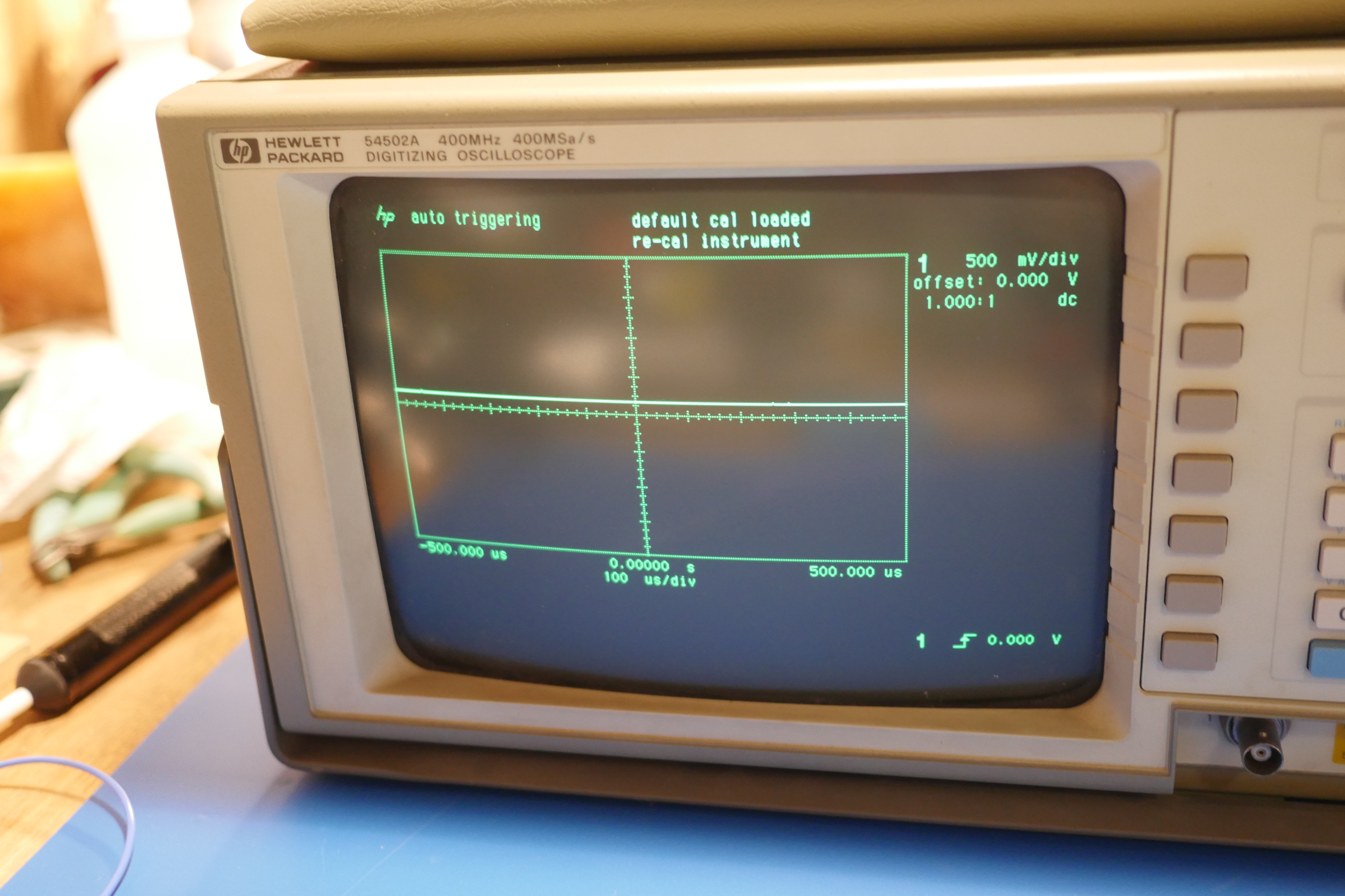
I took it over to the JROWL building (physics department) to test the oscilloscope's functionality, as I had no spare BNC cables or signal generators lying around my dorm. I searched around the physics department for a professor I knew and asked if I could borrow a room and some cables for a few minutes. Shortly after, I setup in an empty physics II demonstration room and plugged in the scope. It booted up without hiccup and passed the hp splash screen. There was an impending doom though as the "default cal loaded" and "recal instrument" errors appeared on top right center of the display. Giving the machine a once-over, I noticed two "recalibration" jacks on the rear of the scope near the mains input.
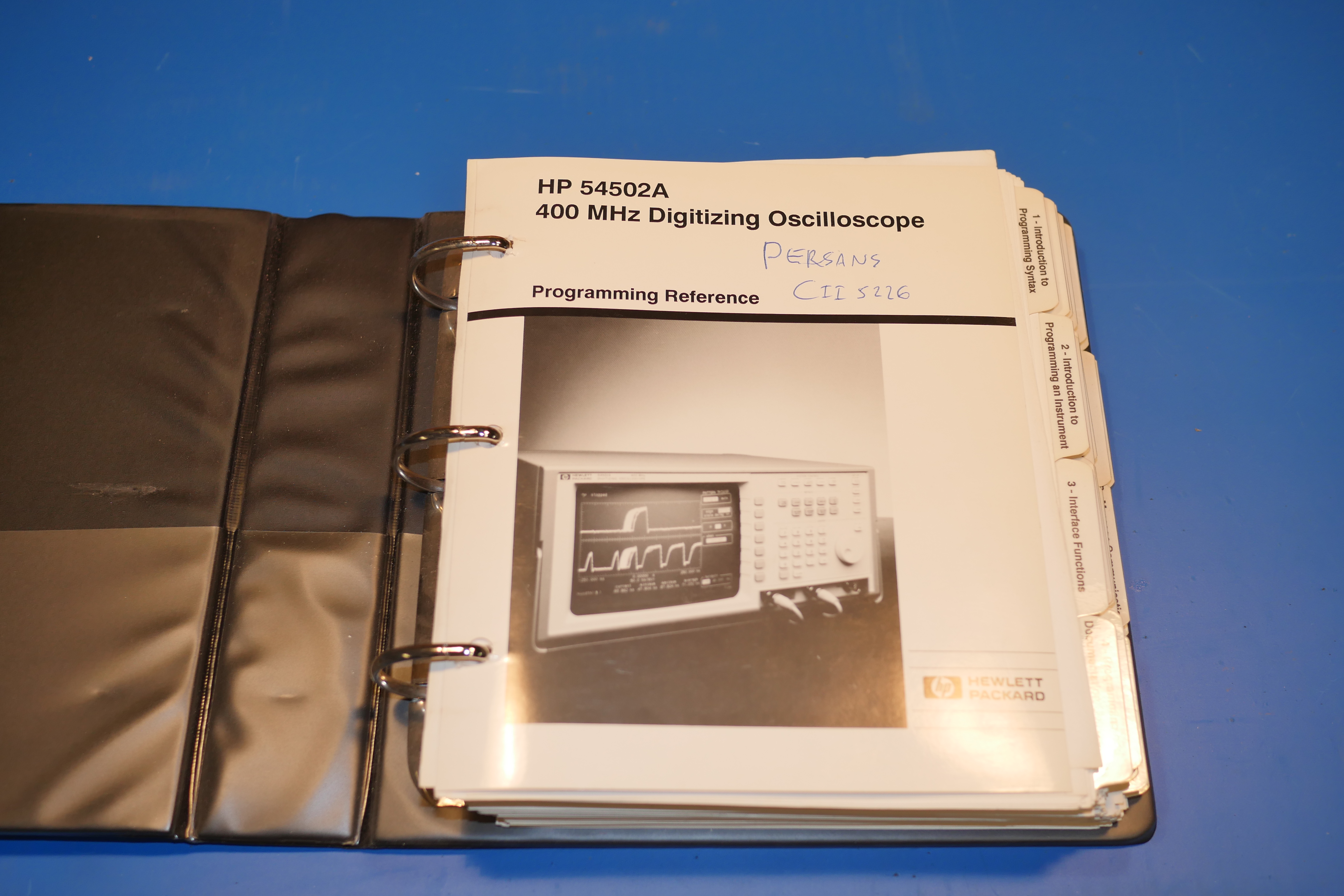
I asked Professor Dwyer if the Physics department had any similar HP Oscilloscopes and if they happened to have any service manuals lying around. To my amazement, the oscilloscope was actually retired from the physics department and was one of the favorite scopes of my past physics professor, Professor Peter Persans, who I respect greatly. He signed off on the unit because it continued to show the same error on bootup regardless of what operation was performed on the scope. He did not have the time to diagnose the problem, so he handed it off to one of his graduate students. The grad student was also puzzled over the problem, so the physics department eventually discarded the scope. Luckily, Professor Persans was in the room next door, and he gladly gave me the owners manual for the HP 54502A!
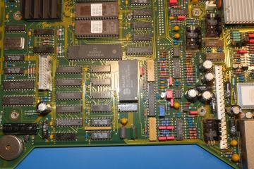
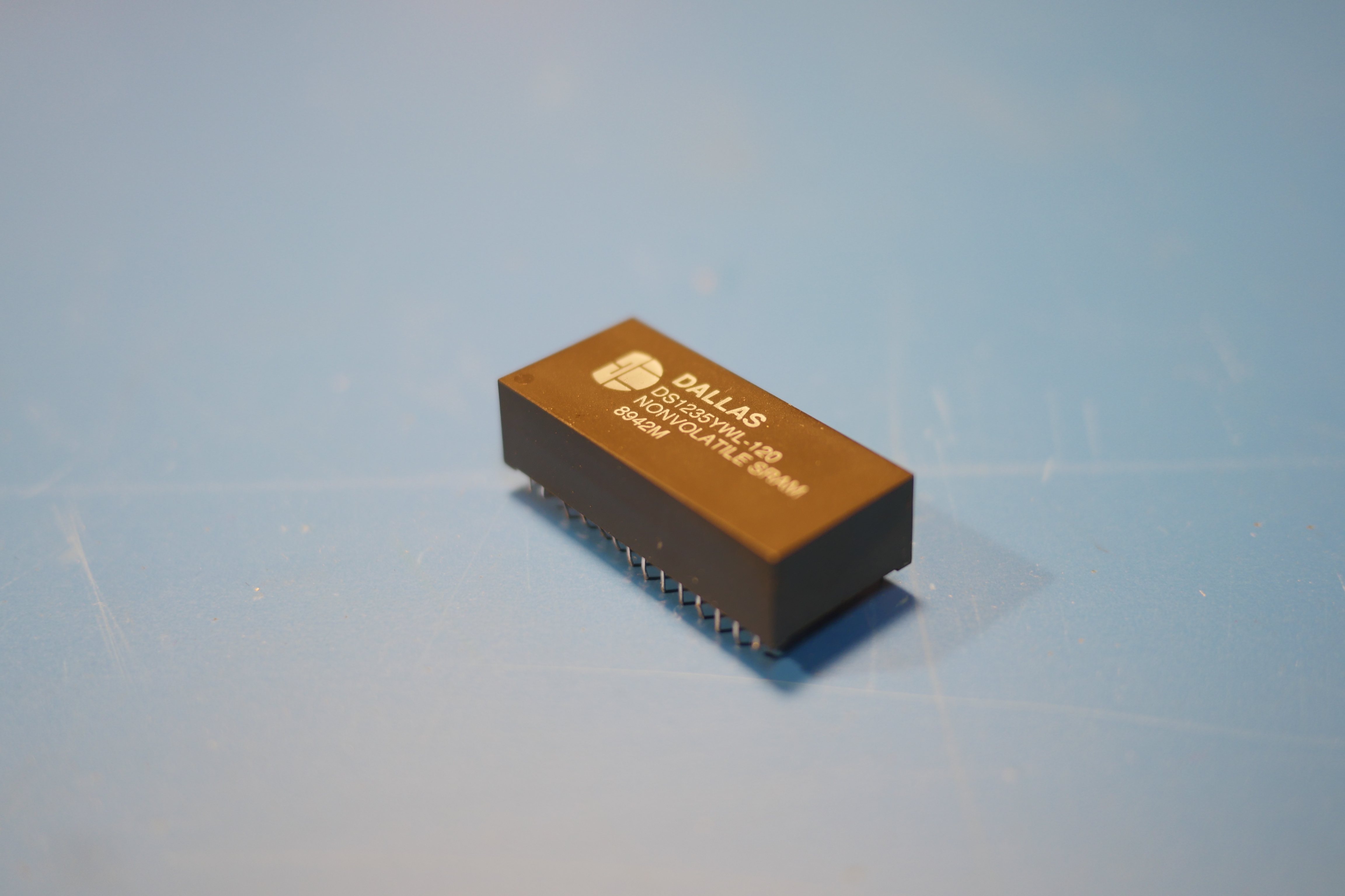
With the manual in hand, I toggled the calibration switch on back to "unprotected" mode and did a recal of the instrument. Eureka! It worked! However, it lost those settings the second I restarted the scope. Bummer. Knowing that old HP scopes were built like tanks, I held onto the scope until I had enough time to thoroughly test and repair it. Unfortunately, the scope sat for around 2 years before I was able to fully bring it back up to snuff. I came across several websites and forum posts on HP 54502A problems, and sure enough, the EEVblog had the answer staring me right in the face. I cannot believe I did not think of it earlier. It was a problem I encountered so often in my childhood hobby of toying with old PCs. The problem comes down to one chip used in the oscilloscope's design: the internal clock battery. I remember these populating EVERY motherboard from my days working with 386/486/Pentium One machines. Talk about a blast from the past!
It has been at least 10 years since I had last seen a Dallas chip used in ANY PCB design. They were simple enough to spot in older boards: a 2 row, black, rectangular package with a big ol' clock symbol on them. Occasionally, they were even socketed for easy replacement. Well, that was the ONE downfall of the HP oscilloscope: it was not socketed. Thus, this project is devoted to socketing the Dallas chip on the HP 54502A oscilloscope and re'caling the instrument.
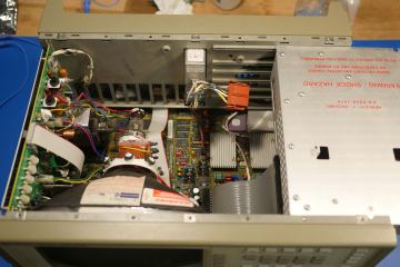
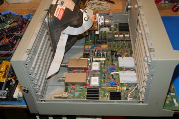
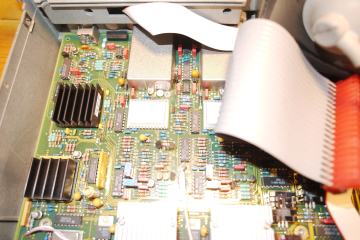
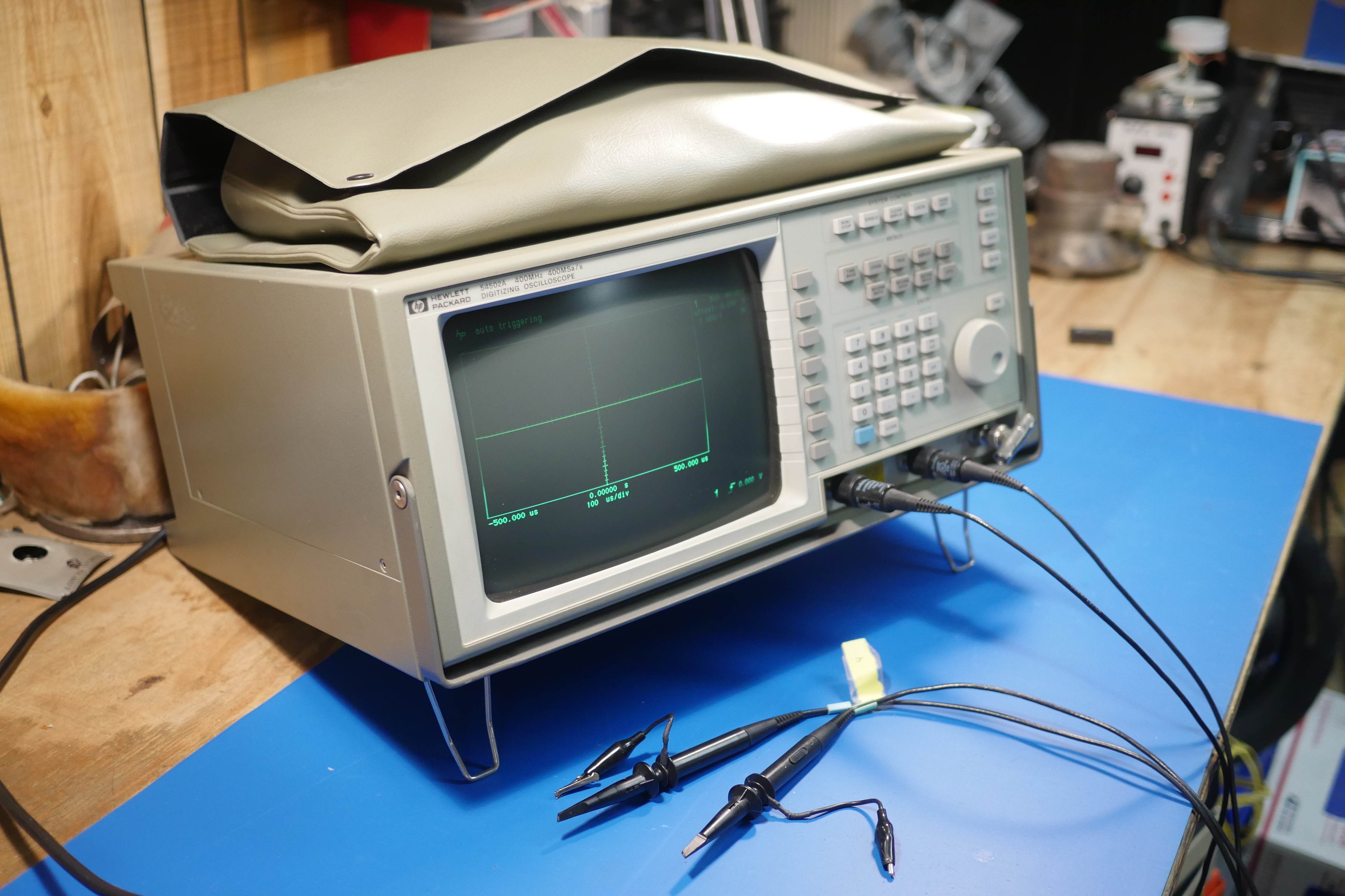
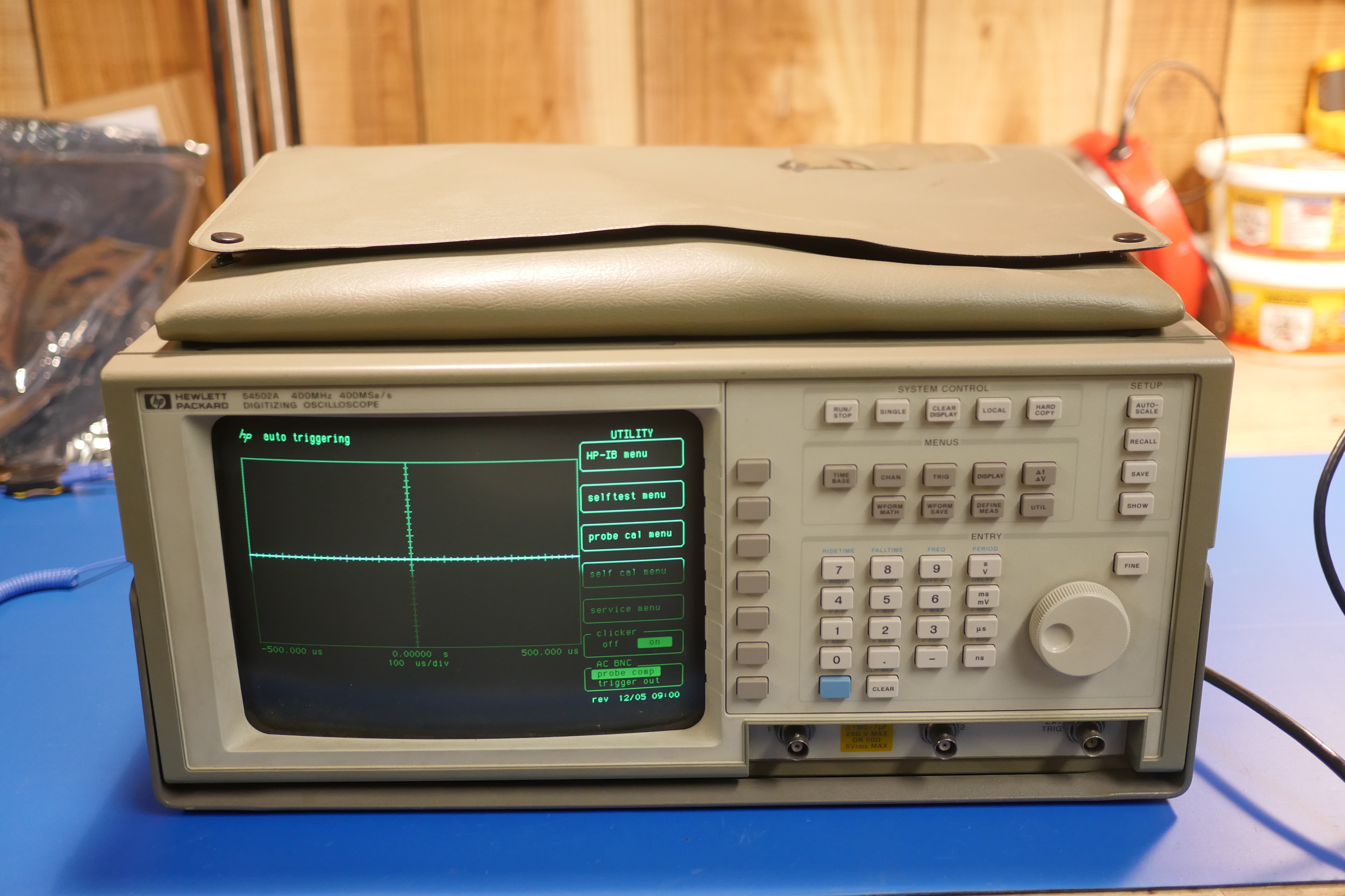
Ok. let's Take a walk around of the scope before I get into the teardown. As you can see, this scope features the very best design ques the 80s had to offer: vertical lines, horizontal lines, and any other straight lines that intersect at 90 degrees! Yes it is very boxy, but there is something to be said about purpose-built design. Everything incorporated in this design has a function and a reason behind it. There are no superfluous curves, dips and bows in the sheet metal. The plastic front end is not over-designed and swoopy. The edges of the screw holes are chamfered, so the Torx screws sit flush with the surface of the unit. It is very boxy, very square and just the way I like my test equipment. The tactile feedback of the button keypad is second to none, and the adjustment knob is very fine.
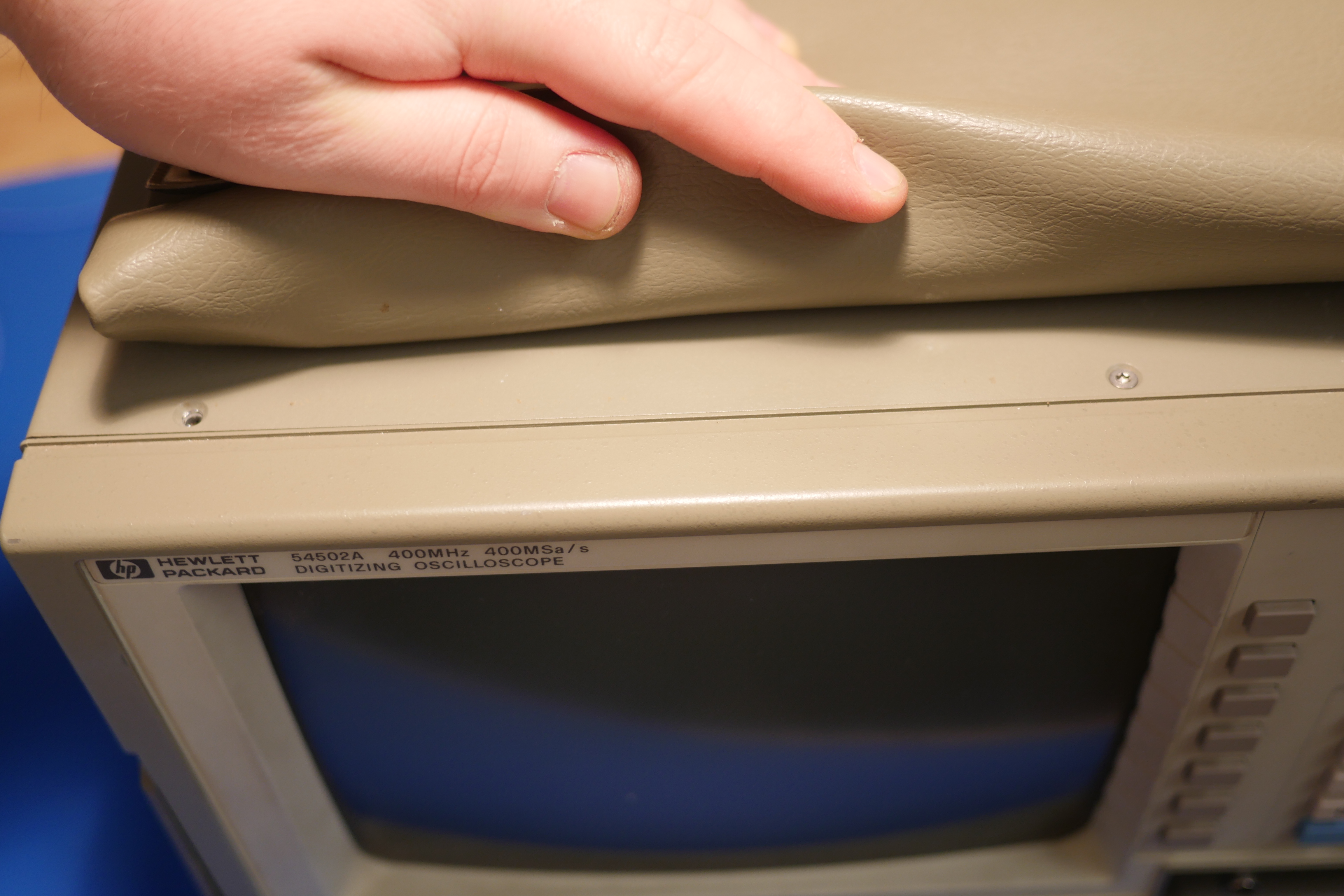
Into the teardown. There are (3) T10 Torx screws lining the front of the top panel, and another 3 on the rear of the top panel. Unfortunately, these screws are not-so-obvious since the component bag covers them. There are an additional (2) Torx 10 on each side of the sheet metal cover.
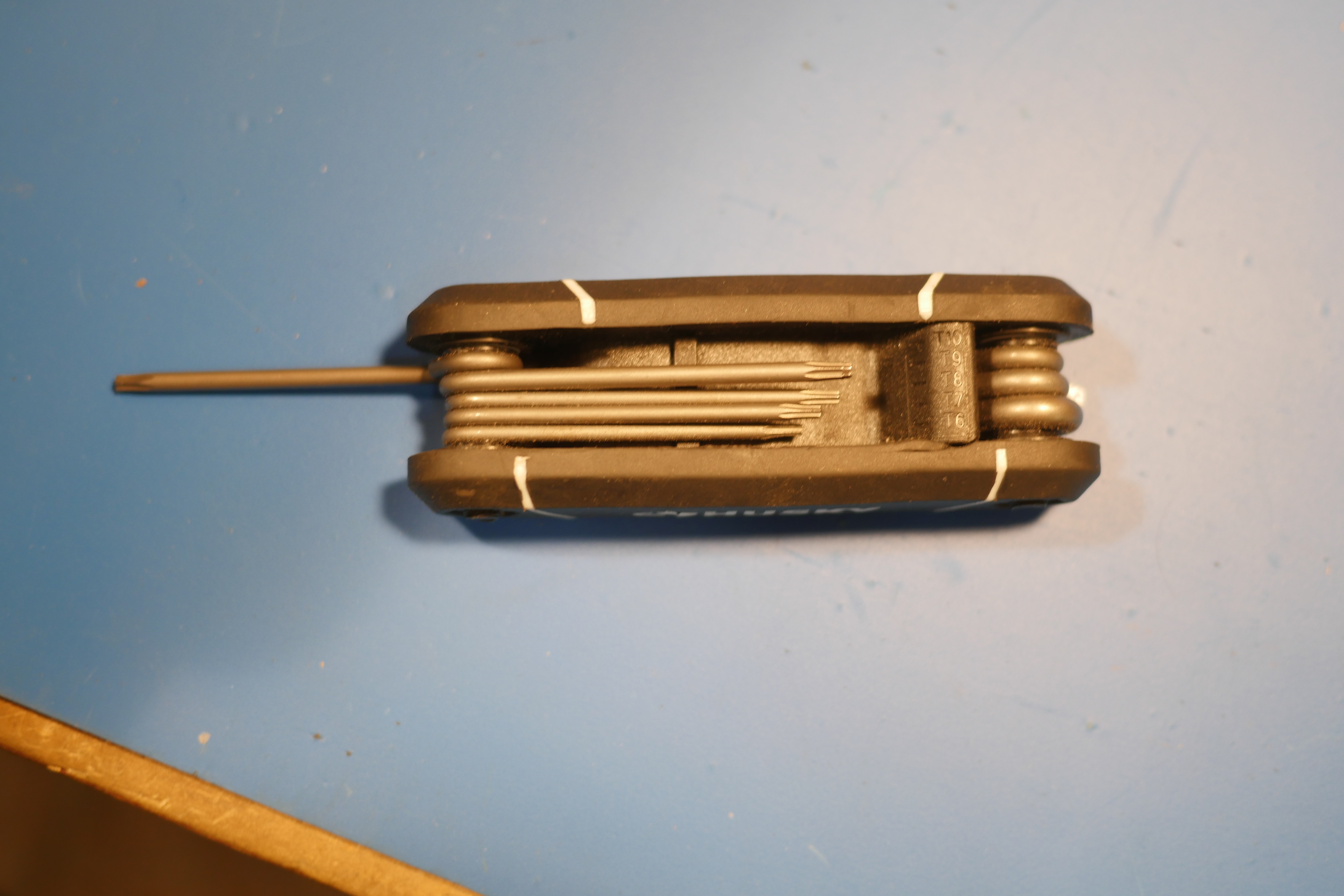
If you haven't realized this by now, having one of these is extremely useful throughout this repair.
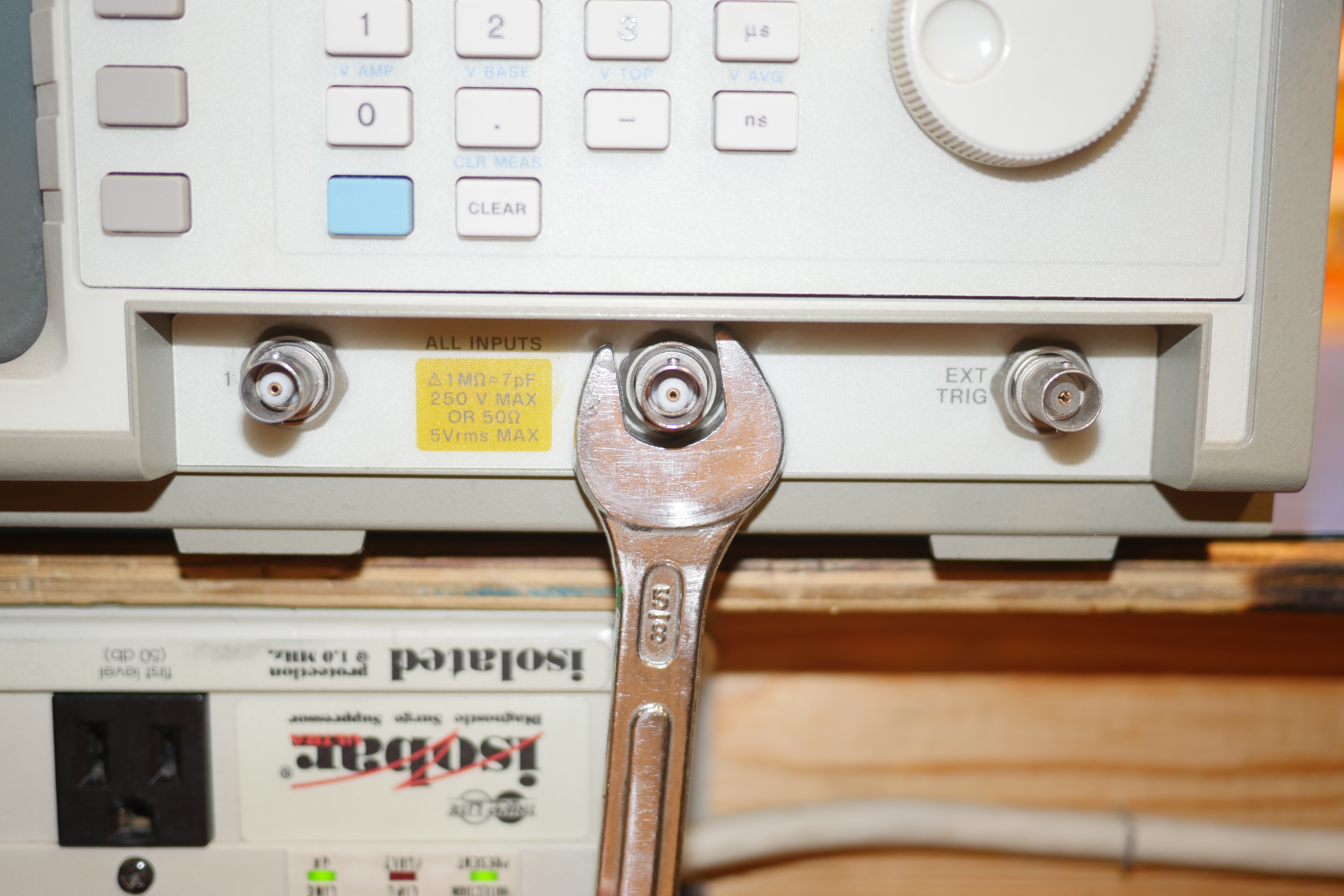
There several more Torx 10 screws around back holding in the rear aluminum baseplate. The next line of attack is removing all of the retaining nuts for the BNC connectors. there is one on every BNC on this unit, to 5 in total. If a 5/8 in open end wrench is good enough for Doc Brown...
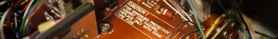
Dallas (DS1235YWL-120) chip that has failed. ran some self tests. sure enough, the scope seemed to work fine.however, I later ran a self-cal, which it failed. I went to service menu --> start cal it then showed: status: executing cal then status: failed cal it then stated: failed time null cal 0000 0000 0000 0001 I wanted to know if this "failed time null" error was because of the Dallas chip or some other problem I must have overlooked.
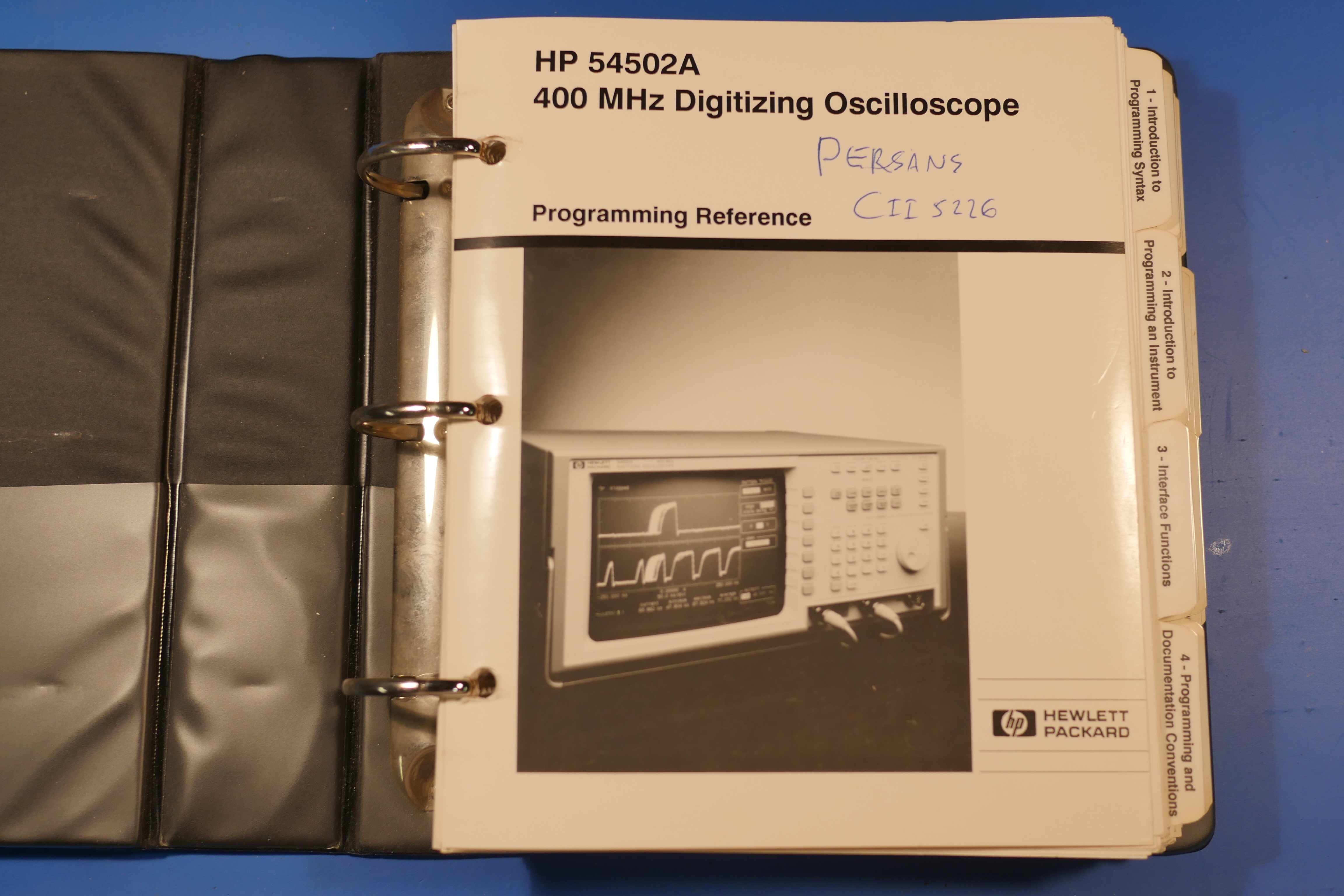
This scope really has some value to me, and I have no plans of discarding it in the near future. There was barely even any dust inside it either! Unbelievable! it also means a lot to me because I was given the original operators manual-binder signed from my former professor, which is something I'm going to keep for a while.
Want more? Here's a behind the scenes look at my workspace and some of the images that did not make the cut to be included in the write-up: