
Adapting Rodenstock TV-Heligon Lens to Micro Four Thirds
One of the shortcomings of smaller image sensors is obtaining adequate exposure in dim lighting situations. Anyone used to sub full-frame cameras or just dull kit lenses has felt this pain. To gain appropriate exposure you'll either have to bump up the ISO, shoot with the lens wide open, add physical light sources to the scene, or just get use a camera with a bigger sensor/better ISO performance.
I decided to just find a brighter lens. Traditionally, bright lenses (f1.4 or less) have a commanding price structure, and fall out of reach of a good portion of the entry level camera audience. A good qualify manual-only f1.4 lens can cost around $120, and for autofocus, north of $400 USD. If you want to dig a bit further and go into the sub f1.2 territory, prices can pick up quickly and approach $600-1000. However, there exists a small subset of lenses that are ~f1.0 or less that are semi affordable. These lenses have their complications and are quite useless unless you are willing to make some compromises and modifications. Yes, I'm talking about the f1.0 - f0.75 X-ray lenses that float around on ebay for less than $100USD. I am one of the crazies who decided to pick one up.
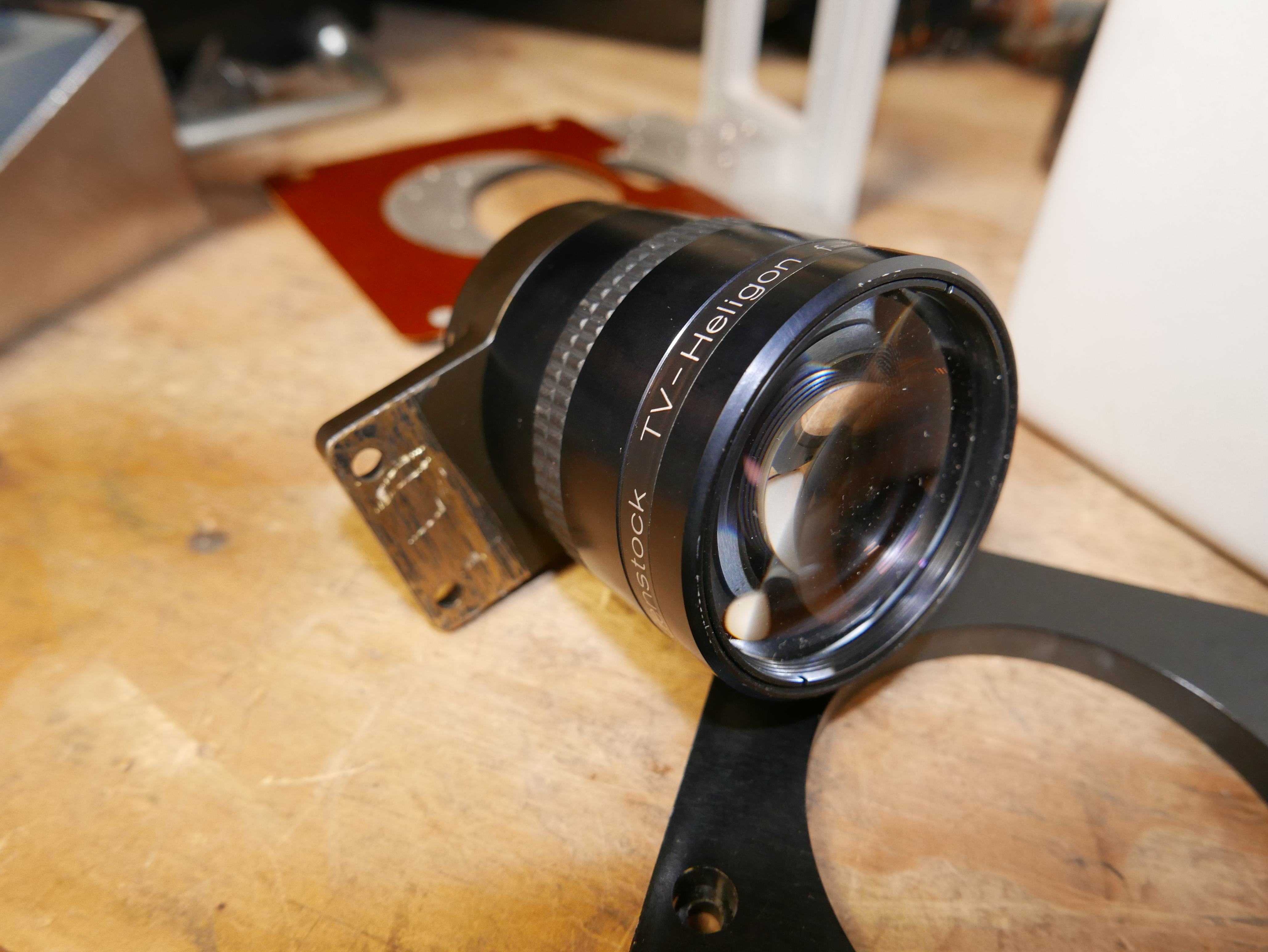
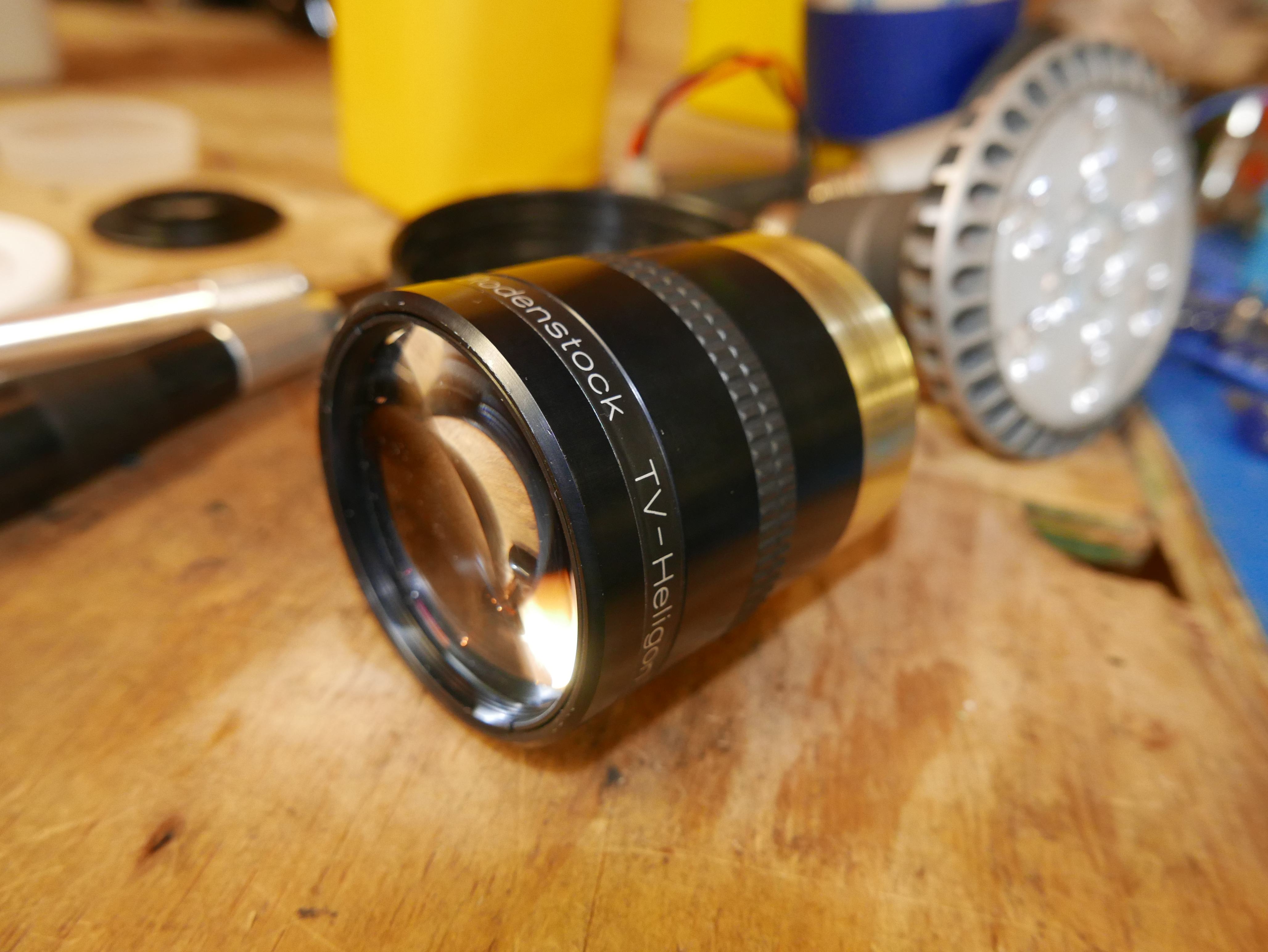
I scored a very bright Rodenstock TV-Heligon lens off ebay a few months ago. This lens is slightly different than other X-ray category lenses. Simply put: It's not marketed just for X-ray machines. The Rodenstock TV-Heligon series of lenses are designed for TV and projection purposes, whereas the XR-Heligon is solely designed for x-ray imaging and medical applications. The XR-Heligon is similar to the De Oude Delft x-ray lenses that float around on ebay. Here's more information on X-ray lenses. These X-ray lenses have quite a following on flickr as well 1 2 3 4 5 6 7. From the flickr photos, it almost seems that the dedicated X-ray lenses tend to have a dull color rendering in comparison to non-Xray lenses. This could be due to specialized coatings or optical materials used in the X-ray lenses to be more susceptible to a wider radiation spectrum. However, this may not be the case at all, as is shown later in this post.
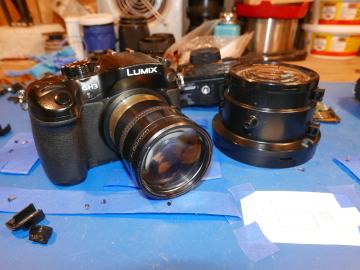
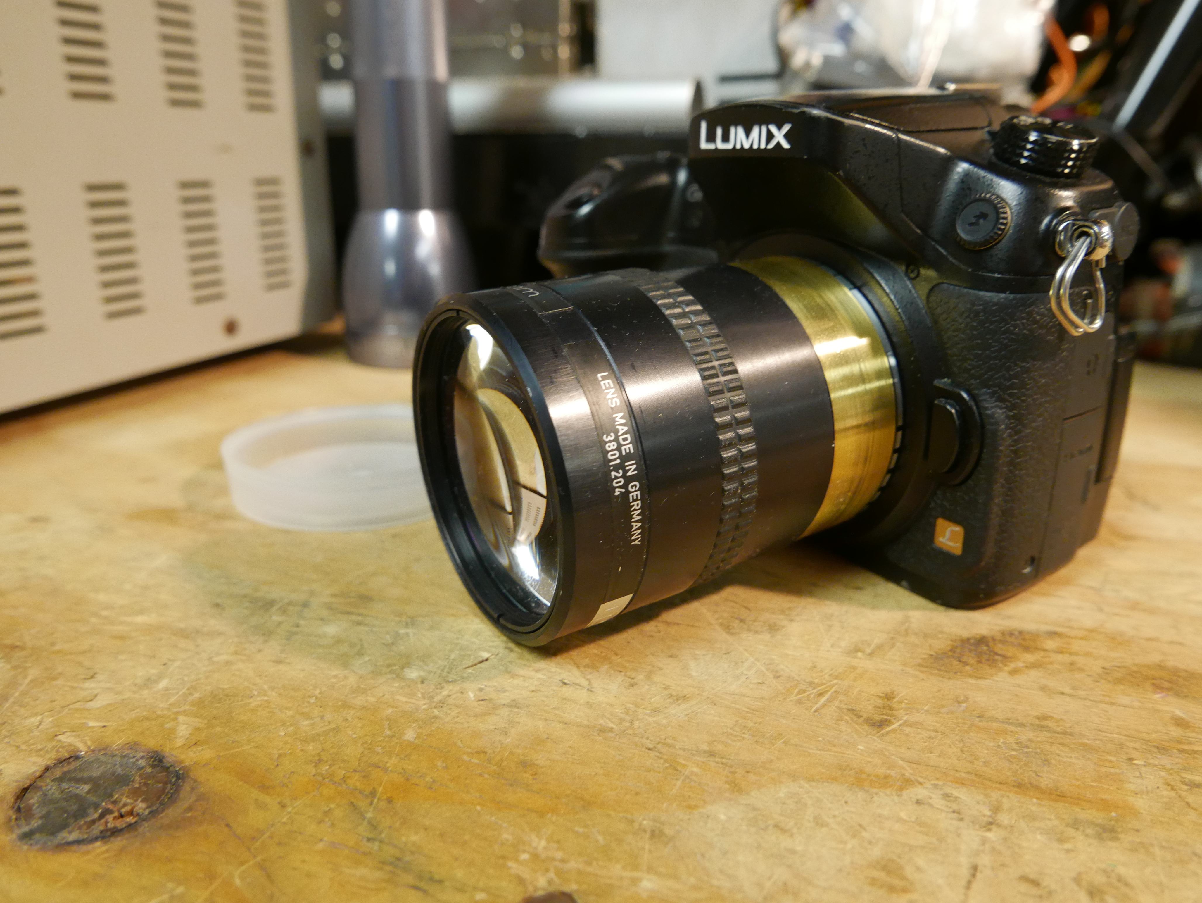
If you hadn't guessed it by now, this is a very peculiar lens. It's a 50mm fixed focal length, fixed focus, fixed aperture, fixed everything lens of unknown aperture. I believe this lens has an aperture of f1.1, as it has the same item number (3801.204), and very similar exterior geometry to the Rodenstock 50mm f1.1 TV-Heligon lens in this ebay listing. It is interesting how the ebay lens is threaded closer to the front of the lens and has a machined groove in the middle, unlike mine. Huh.
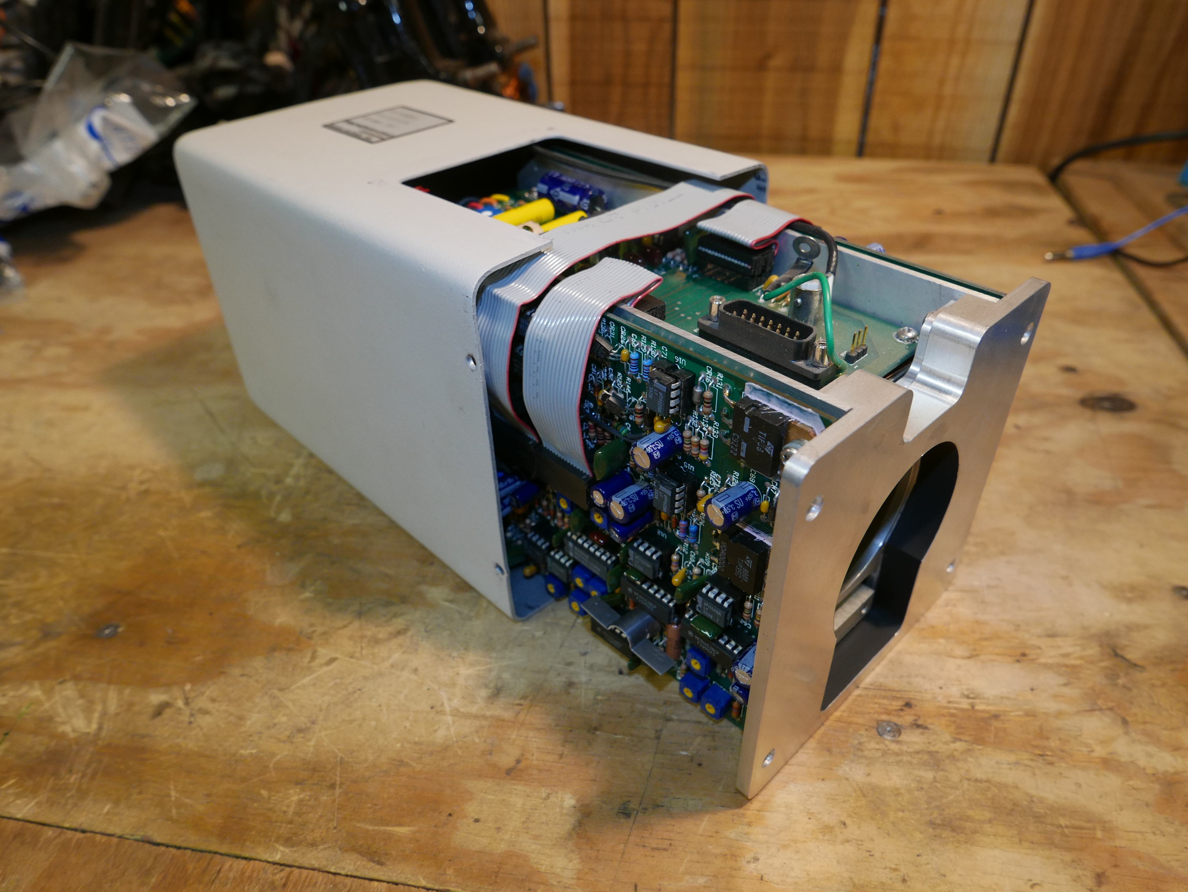
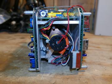
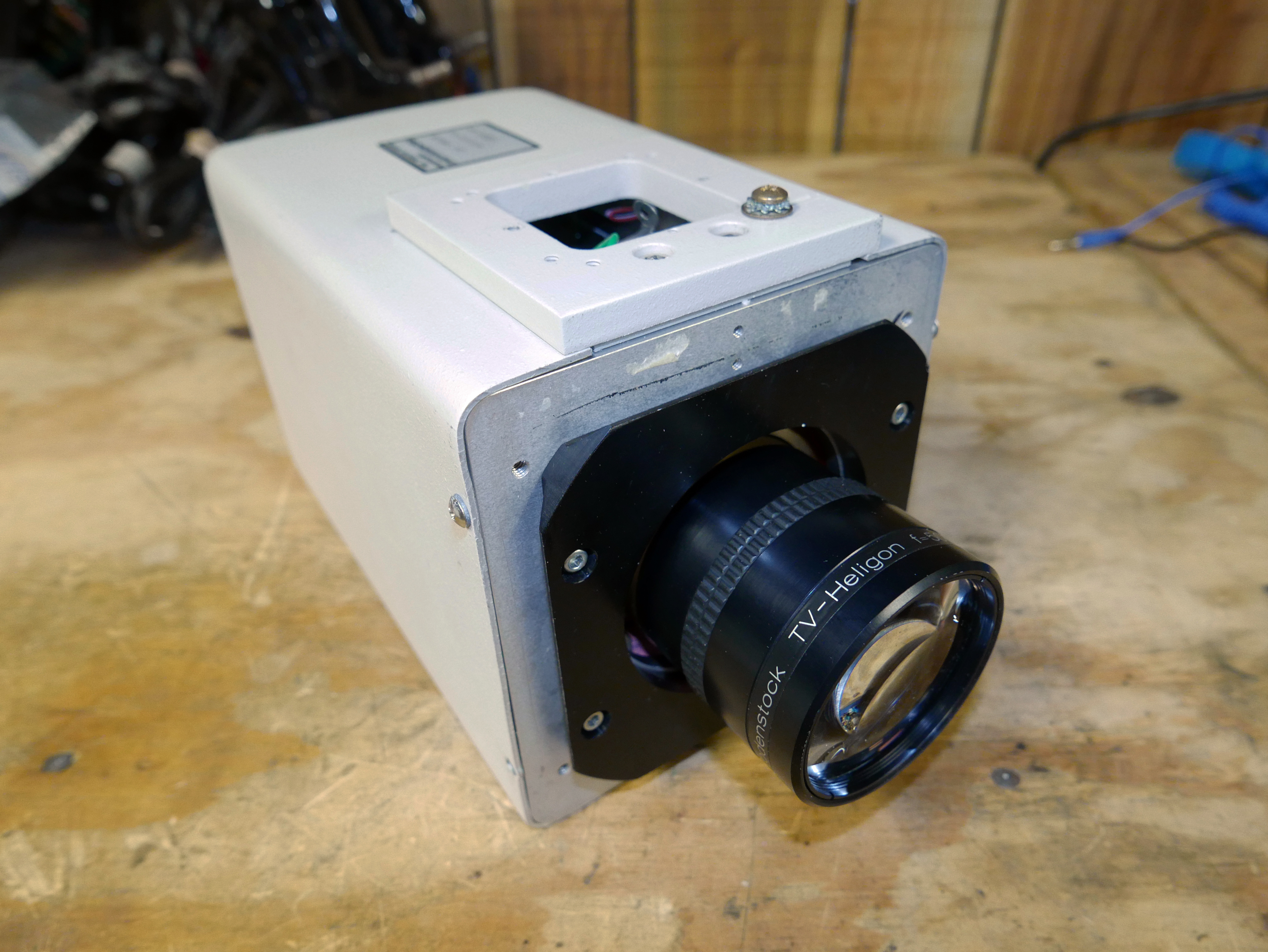
I didn't find the lens by itself. Instead, it came as part of a Fischer Imaging TV camera. I only found the listing by chance, and it came up as a "suggested item" on ebay after my weekly rounds of machine vision camera searches. Here is another listing if anyone is curious. Fischer Imaging developed live TV cameras for medical applications. No, this is not the your-school-only-approves-this-vendor Fisher Scientific, but Fischer Imaging. Fischer Imaging was a branding name used by Syracuse Scientific, a medical device company. It looks like this unit was part of their Fluorotron line of Live TV Cameras used for x-ray imaging.
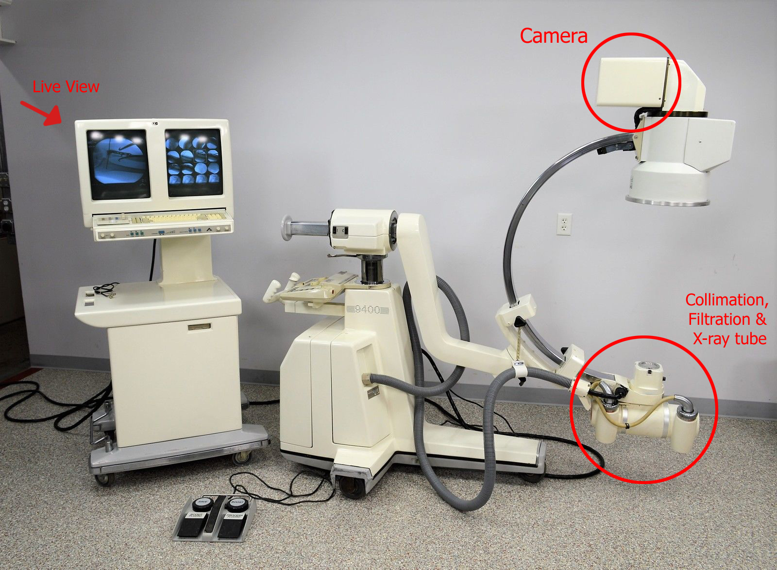
With how specific and odd this item is, you wouldn't find it surprising that the camera would literally show up in another ebay listing, would you? Well here it is! This is an ebay listing from new life scientific who graciously allowed me to use this photo for this article. Thanks guys!
It looks like this may be a slightly older Fluorotron than the one my Fischer came from, but the principle is the same. The Fischer camera would be mounted where it is circled in the photo and would allow for live footage to be captured from a patient's x-ray. The x-ray source would be initiated by a doctor, passing the radiation through the plastic or carbon fiber patient table, through the patient to the camera. Pretty neat huh?
Since this is a camera developed for radiography/Fluoroscopy purposes, one may be a little bit concerned that the lens may be 'activated' or mildly radioactive from extensive use in an x-ray Machine. This is a perfectly valid concern. It is worth performing a quick test to see if the lens is truly radioactive. The quickest way to do this is to setup your micro four thirds camera with the lens in question, put something black over the front of the lens, cover any light openings, put it in a dark room and set the camera to 30sec exposure. This should yield a perfectly black picture. If you see areas of spiked light, clusters of gray or white spots, there is a good chance the lens is partially radioactive. There is some method to this madness, as current day Fluoroscopes are straight up CMOS or CCD sensors. Of course, you could just go out and get a Geiger counter. Keep in mind, some lenses are inherently radioactive, such as some Canon FD S.S.C lenses and Pentax f1.4 lenses since they were composed of glass elements with thorium oxide components. More info on radioactive lenses can be found HERE. Luckily, my lens rendered a black image, so everything's a go.
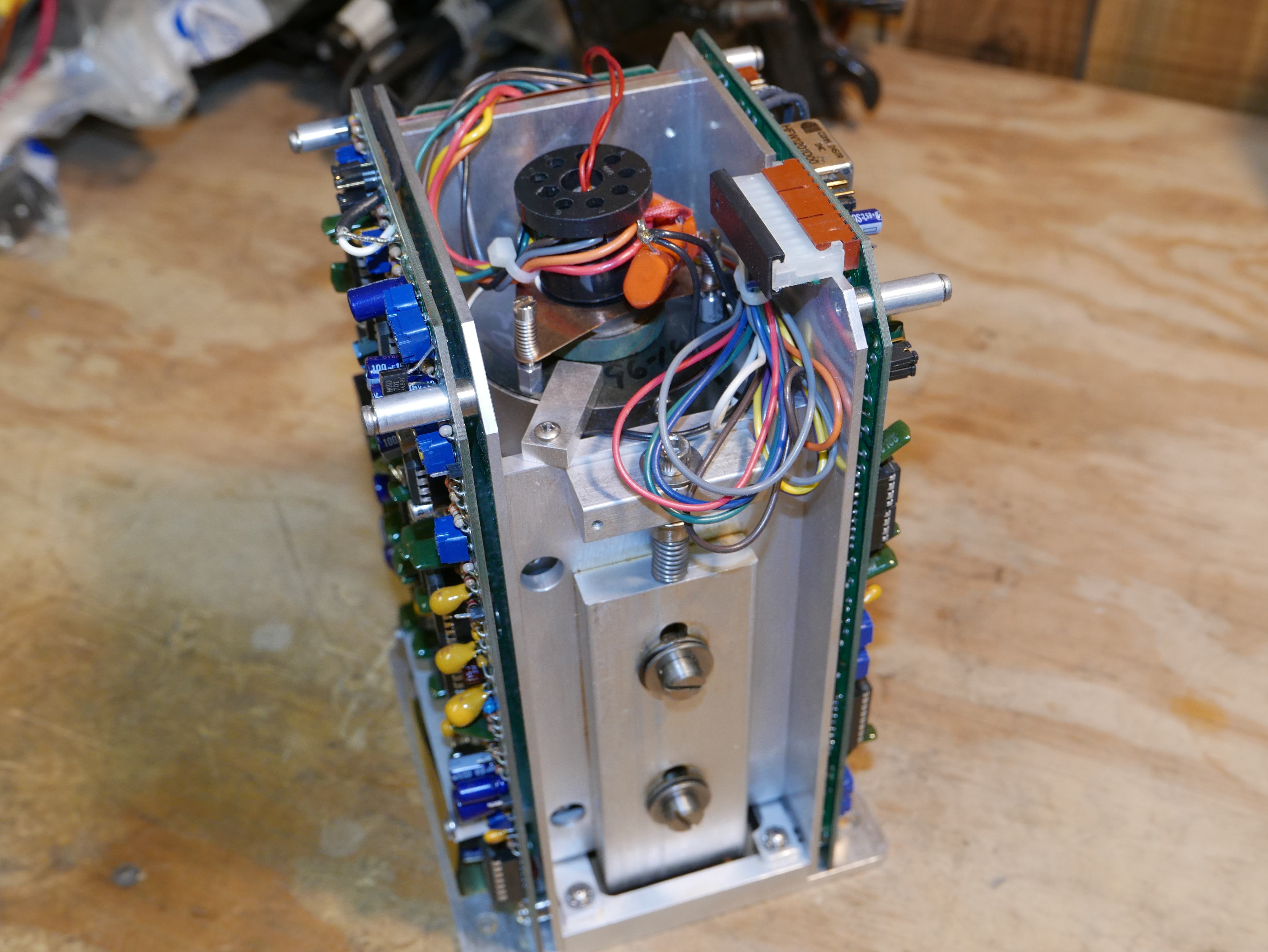
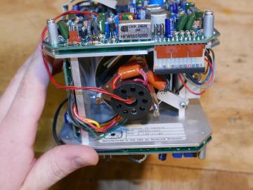
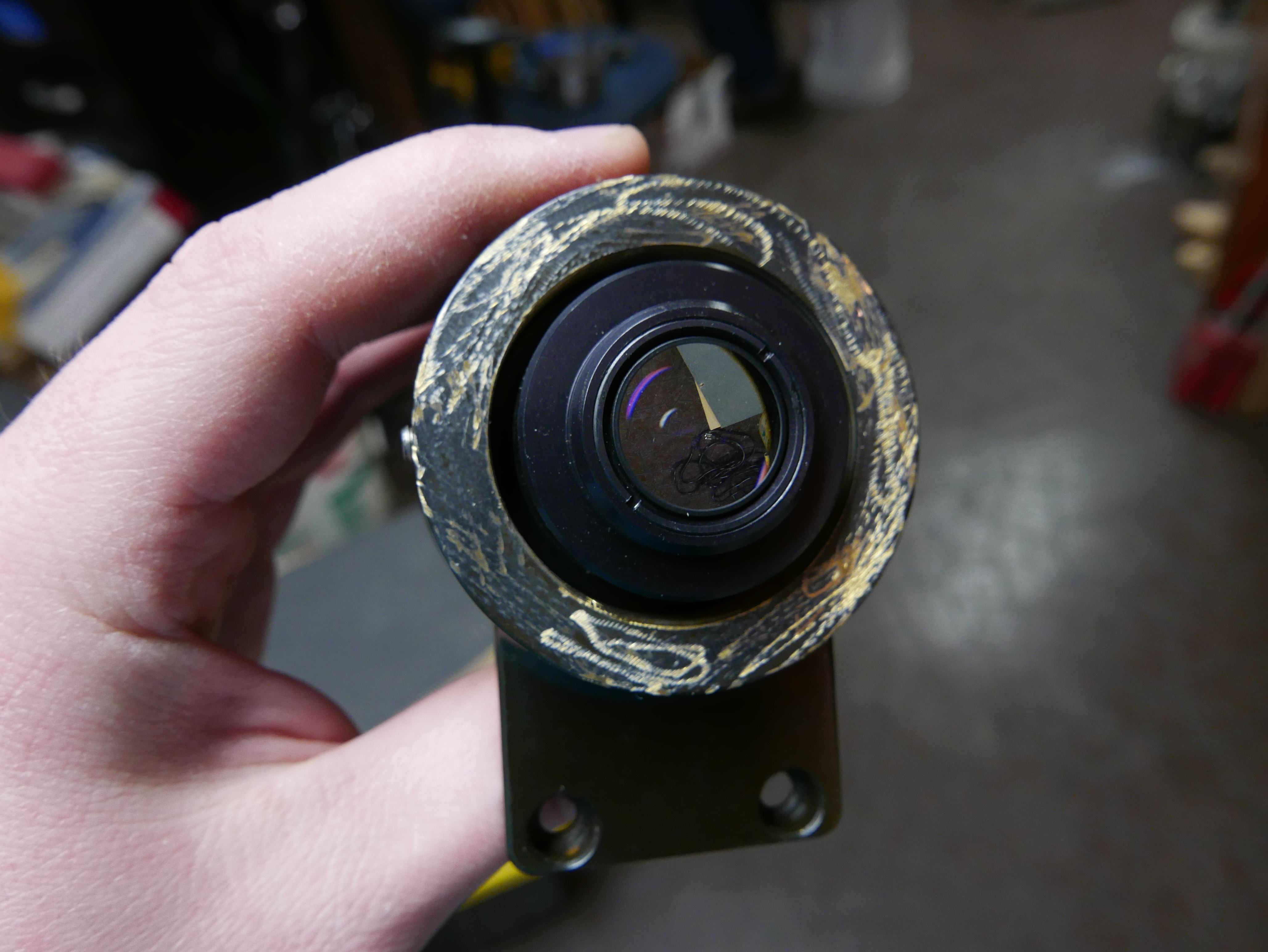
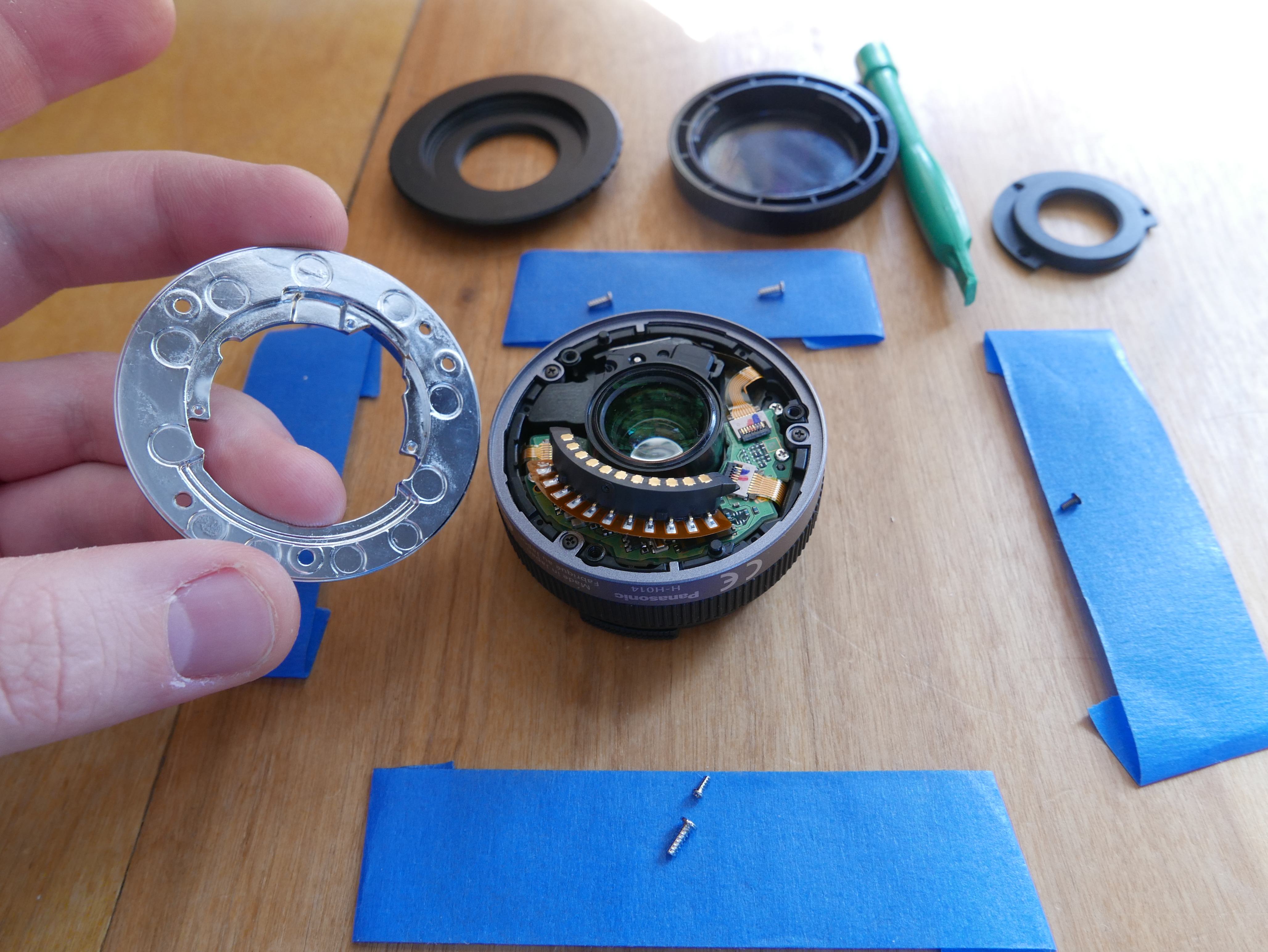
Interestingly enough, the Fischer Imaging camera was not a traditional CCD or CMOS camera. You can see the end of the electron tube and the 9 pin socket. It is a Cathode-Ray tube based camera. If there's enough interest, I'll test it out sometime in the near future and see if it still works.

The model# SS750 / 1023 hints that this camera has 750 lines or horizontal scanlines in terms of resolution. Of Course, I could be totally wrong. Maybe I really should test it out :D.
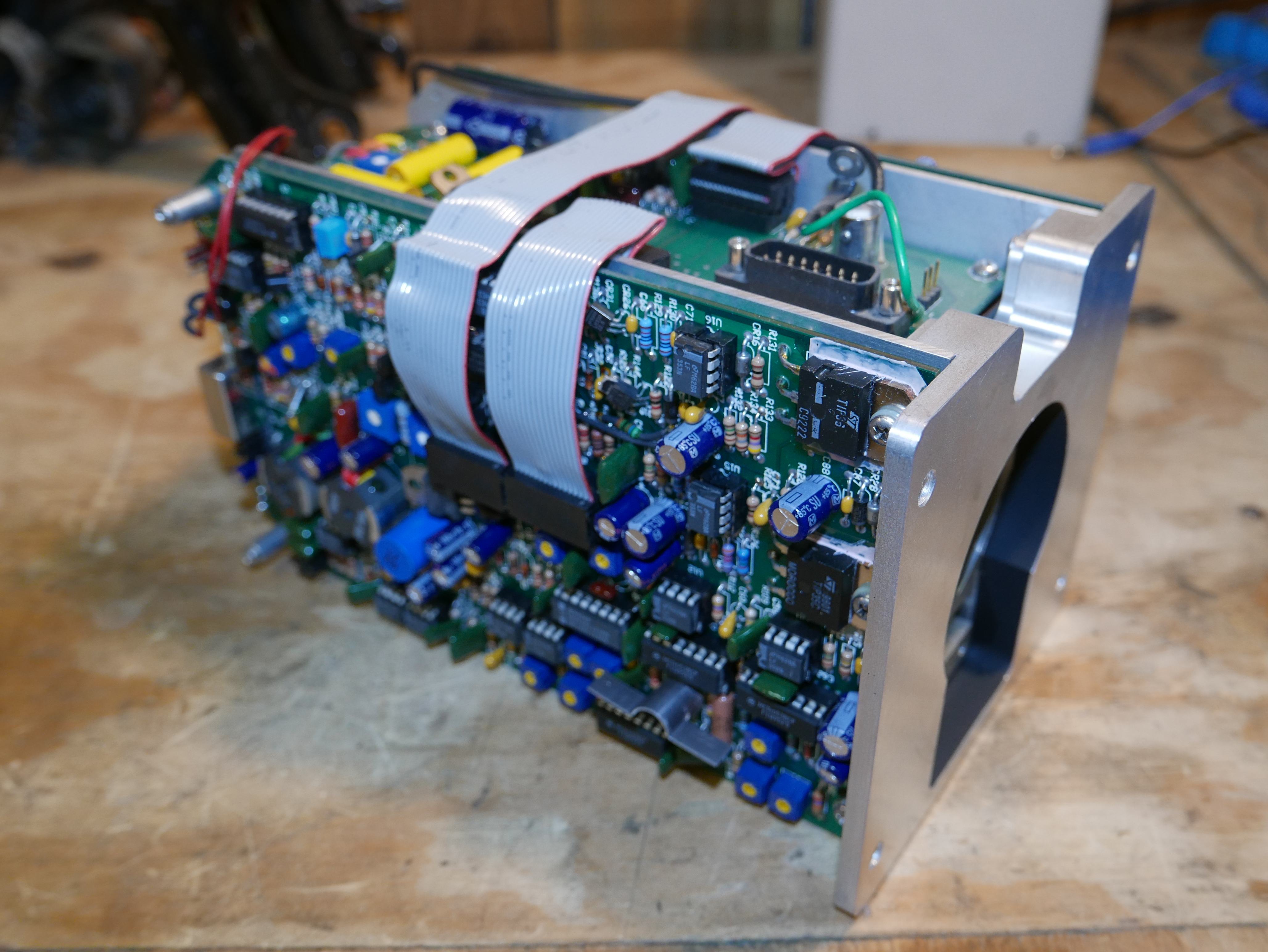
It almost looks like this camera was a precursor to the ubiquitous C-Mount machine vision cameras that are used for quality control purposes in large scale manufacturing today. This is an interesting conclusion, as the camera did not use the standard C-mount or CS-mount lens mounts commonly found in machine vision cameras, but rather something custom.
It is certainly a very weird and specific piece of equipment. Oh and for full disclosure, that rubber ring on the outer diameter of the lens did not turn out to be a focus ring. It is for decorative purposes. Bummer.
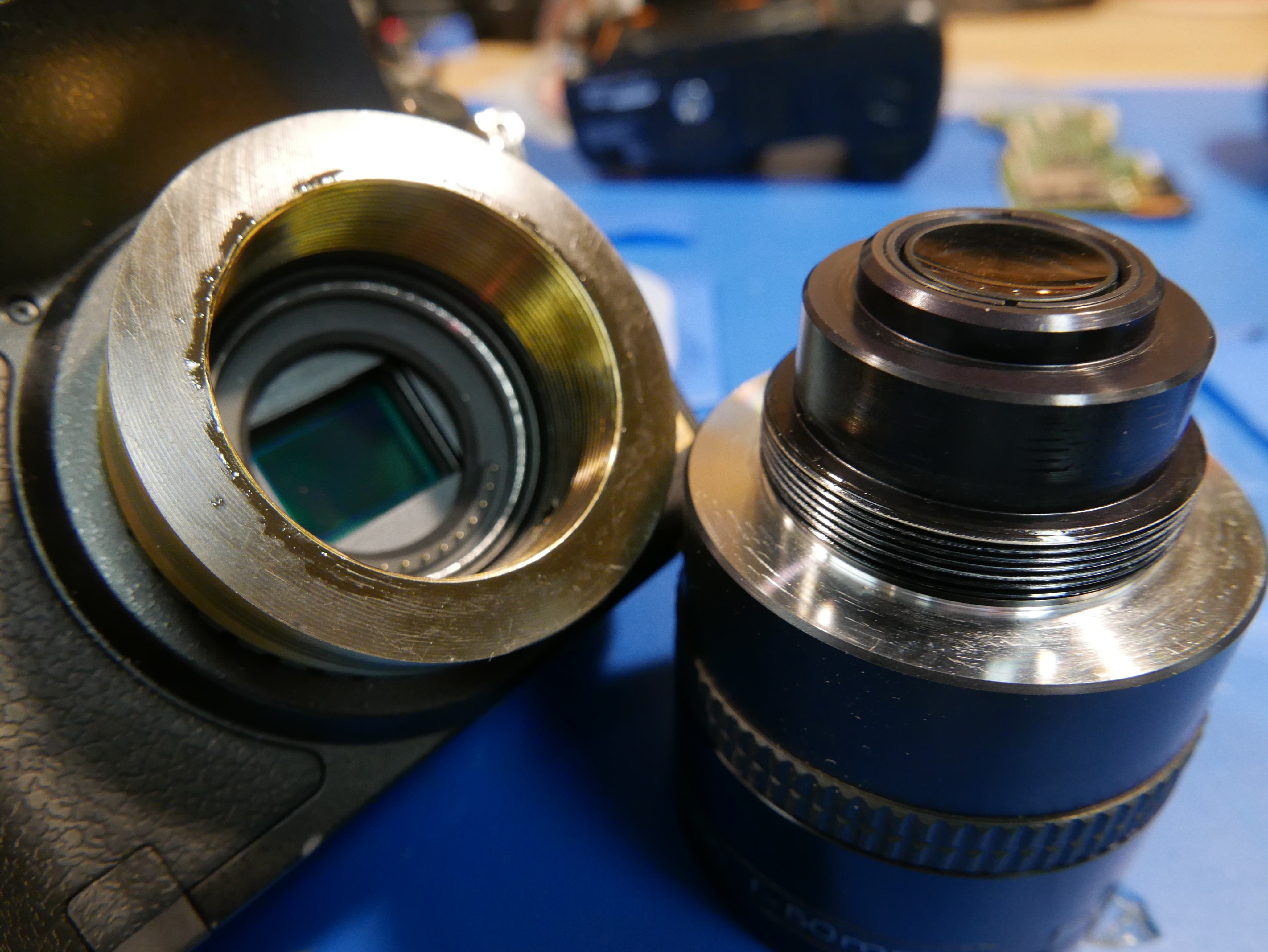
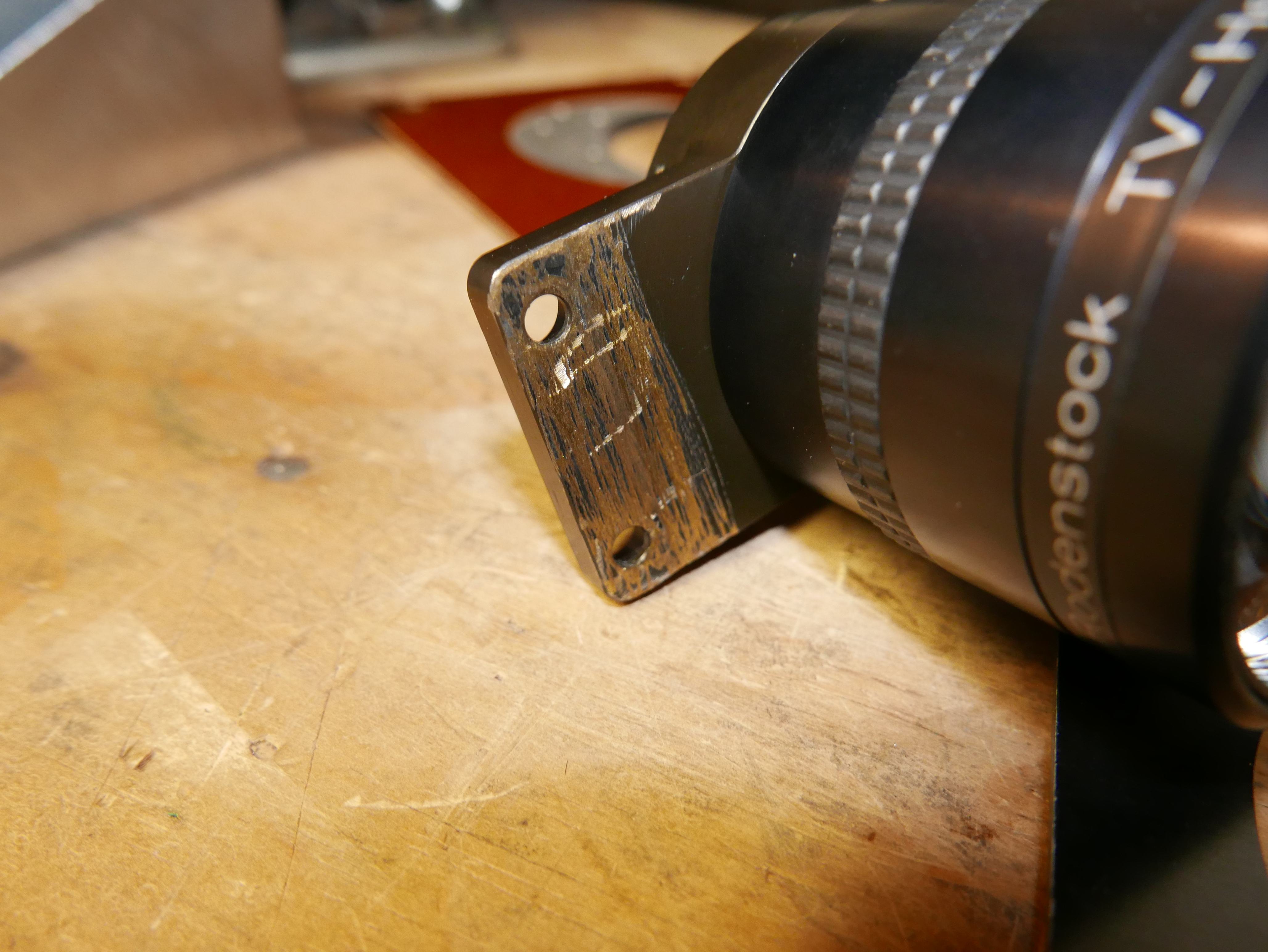
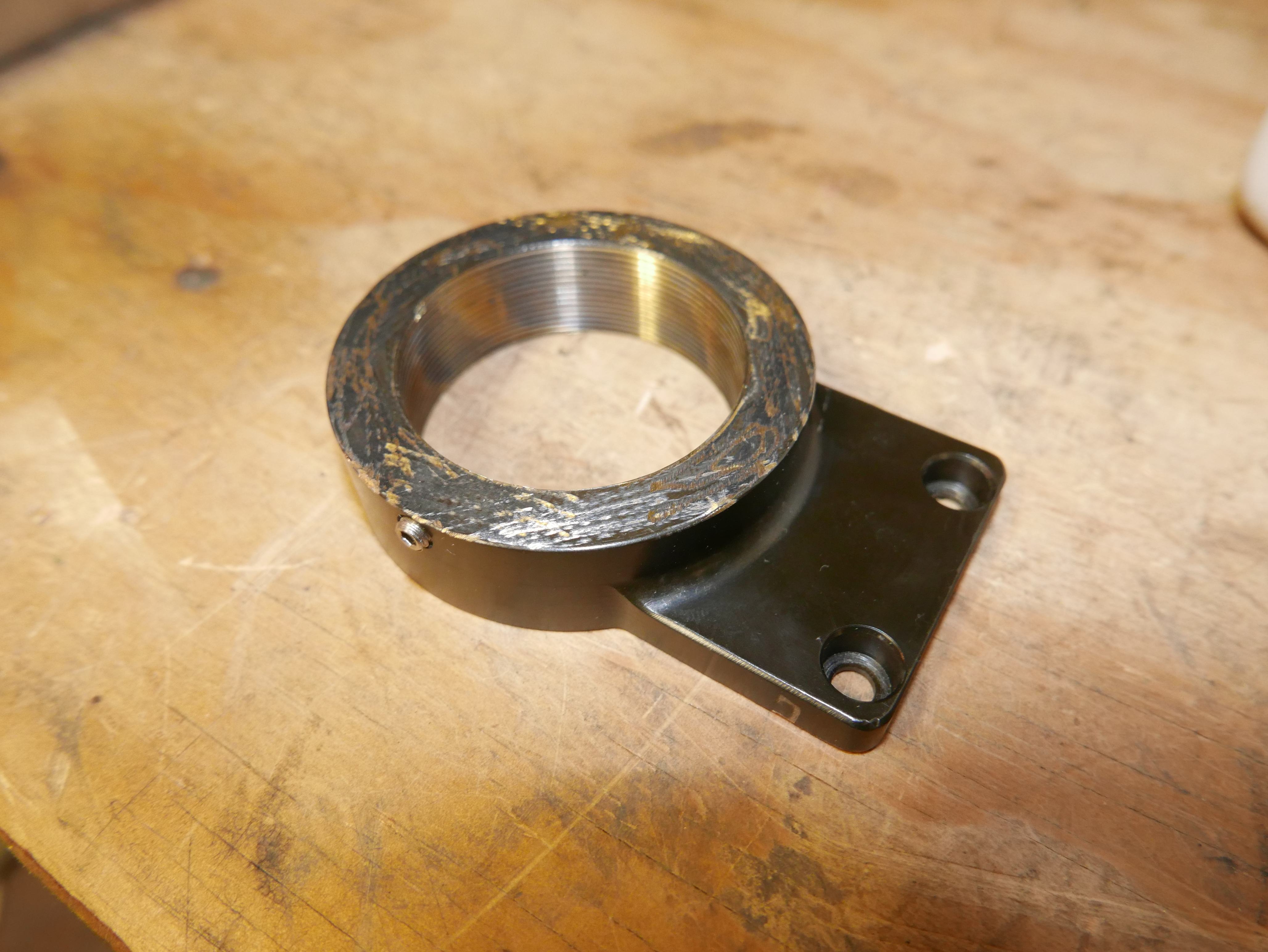
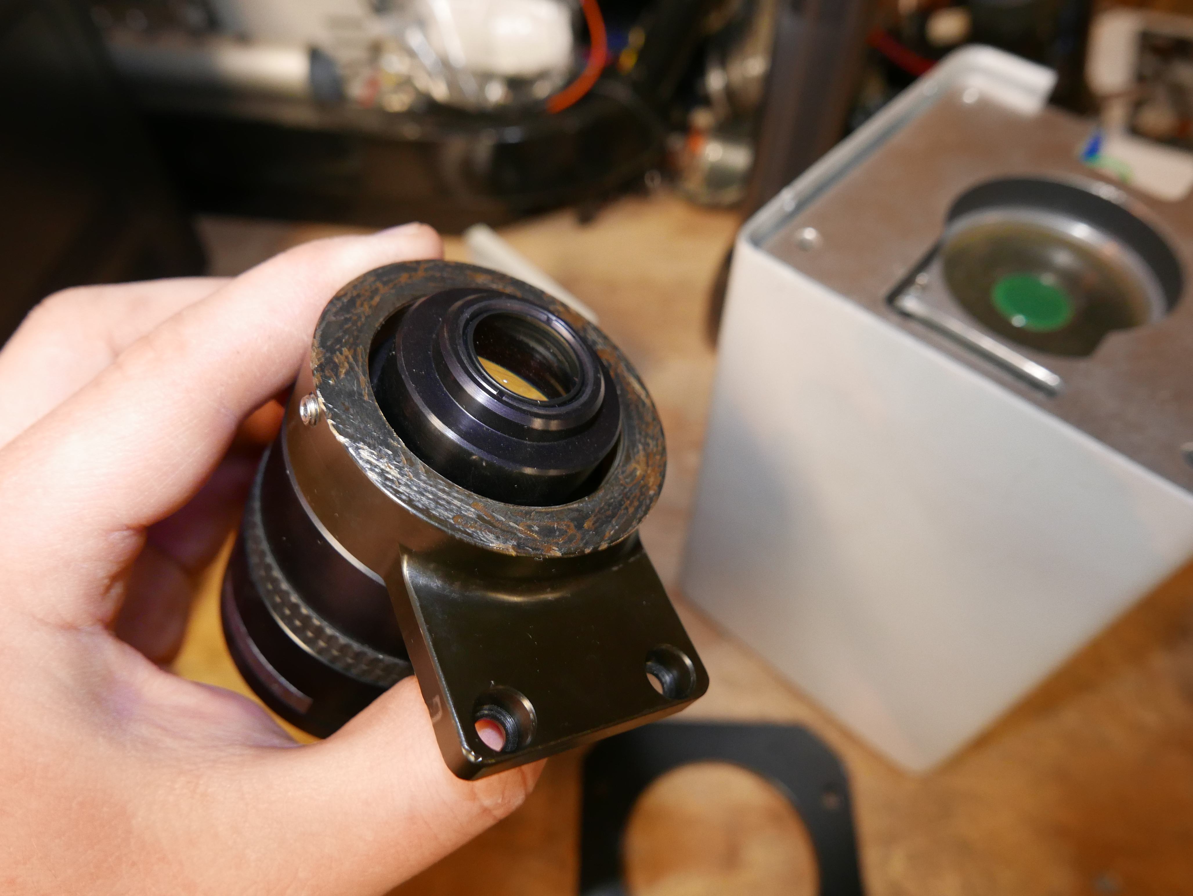
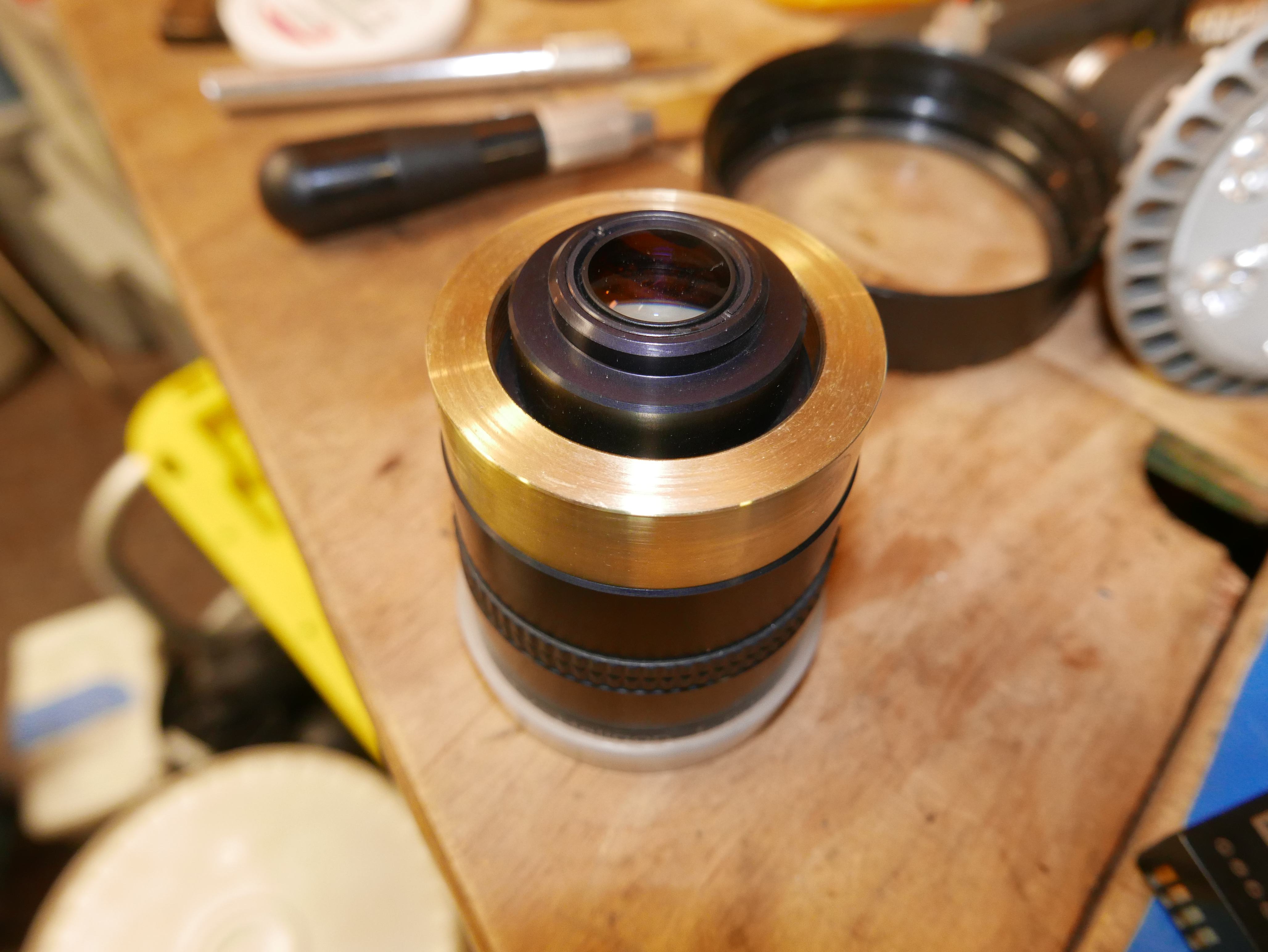
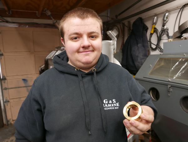
After unscrewing the lens from the camera, I noticed that I'm not the first one in (aww mann). The lens is mounted to a brass block which has been bored, threaded and milled to fit inside the camera cavity. The block just so happens to be horrifically sanded by the previous owner to achieve a closer flange depth from the reference imaging plane.
It looks like someone took a 60 grit belt sander to the mounting face of the brass block. COME ON. There is no way a company would have shipped something this poor in nature. We're talking about brass, one of the easiest materials to machine.

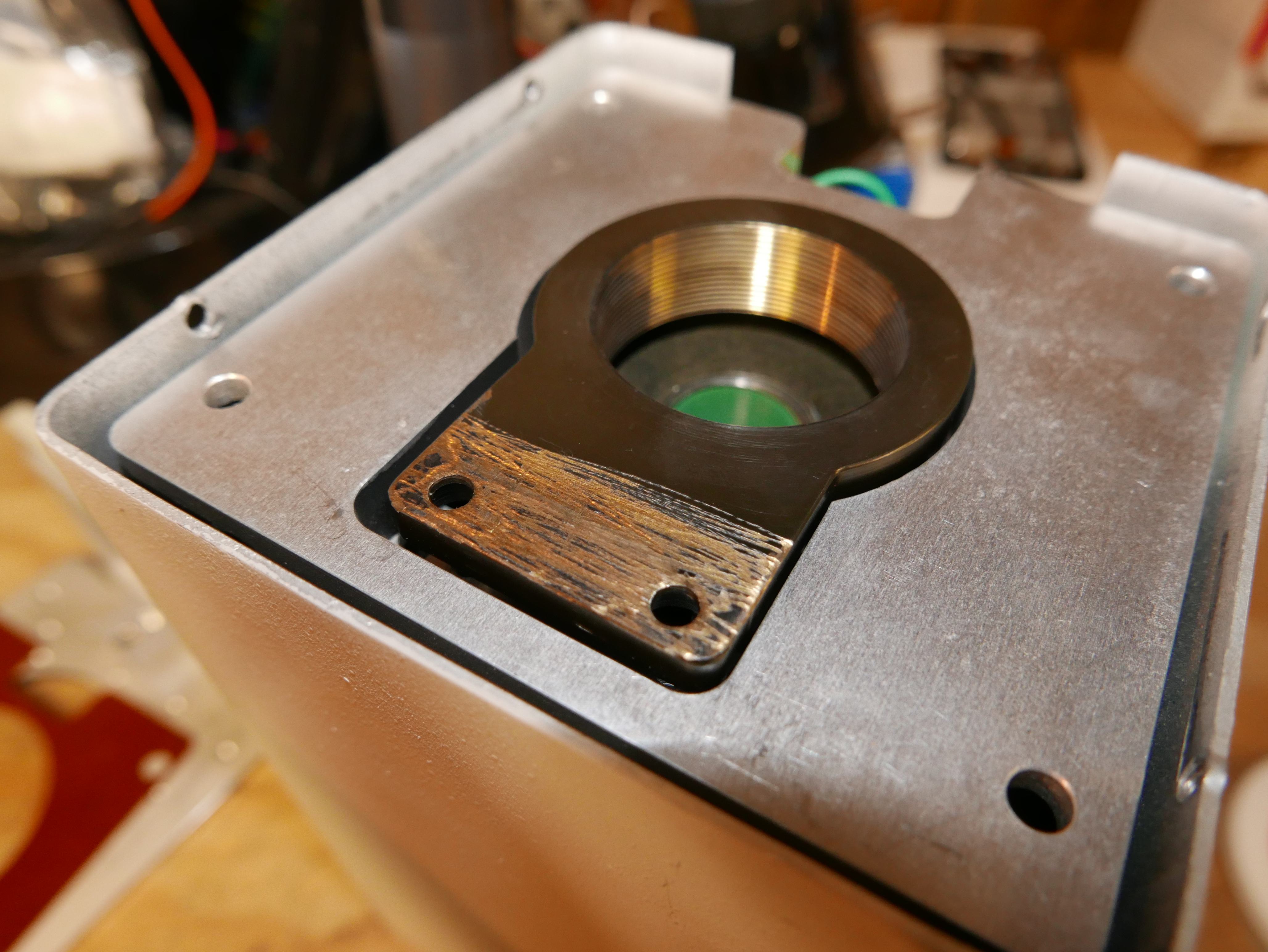
It is also unlikely that this was the initial condition as a fiberglass shim of uniform thickness is sandwiched between the front exterior angle bracket on the camera and the rest of the camera assembly.
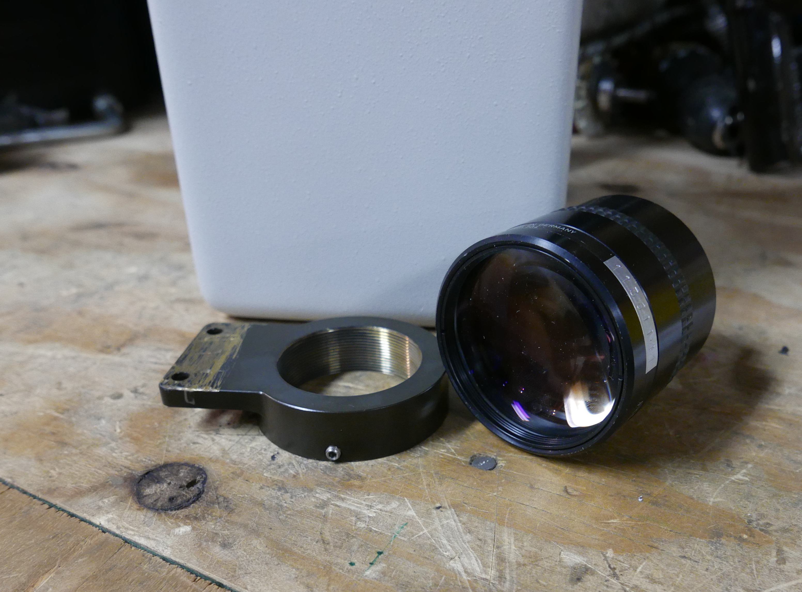
Onto the interesting part. Adapting a lens to a different mount usually requires a bit of modification, machining and patience. This lens is no exception. There are a few approaches one can take to the modification process: machine the lens to a desired geometry and make an adapting part that mates to that desired surface, use the mounting geometry that the lens previously used and make a new mating end, or go full ham and build an entirely new lens shell. As much as I would love to go full ham on this, I decided that it would be best to just modify the mating threaded mount that the lens used inside the camera.
Before the machining process began, I needed to make a few crucial decisions.
- How large is the lens image circle? Will it be enough to fully cover the image circle of my chosen camera system (Micro Four Thirds)?
- Is anything in frame in focus? How will I focus? What type of shots will I be using this lens for?
- Am I going to machine the Micro Four Thirds mount out of the threaded brass mount, or fasten a pre-existing Micro Four Thirds mount the the brass part?
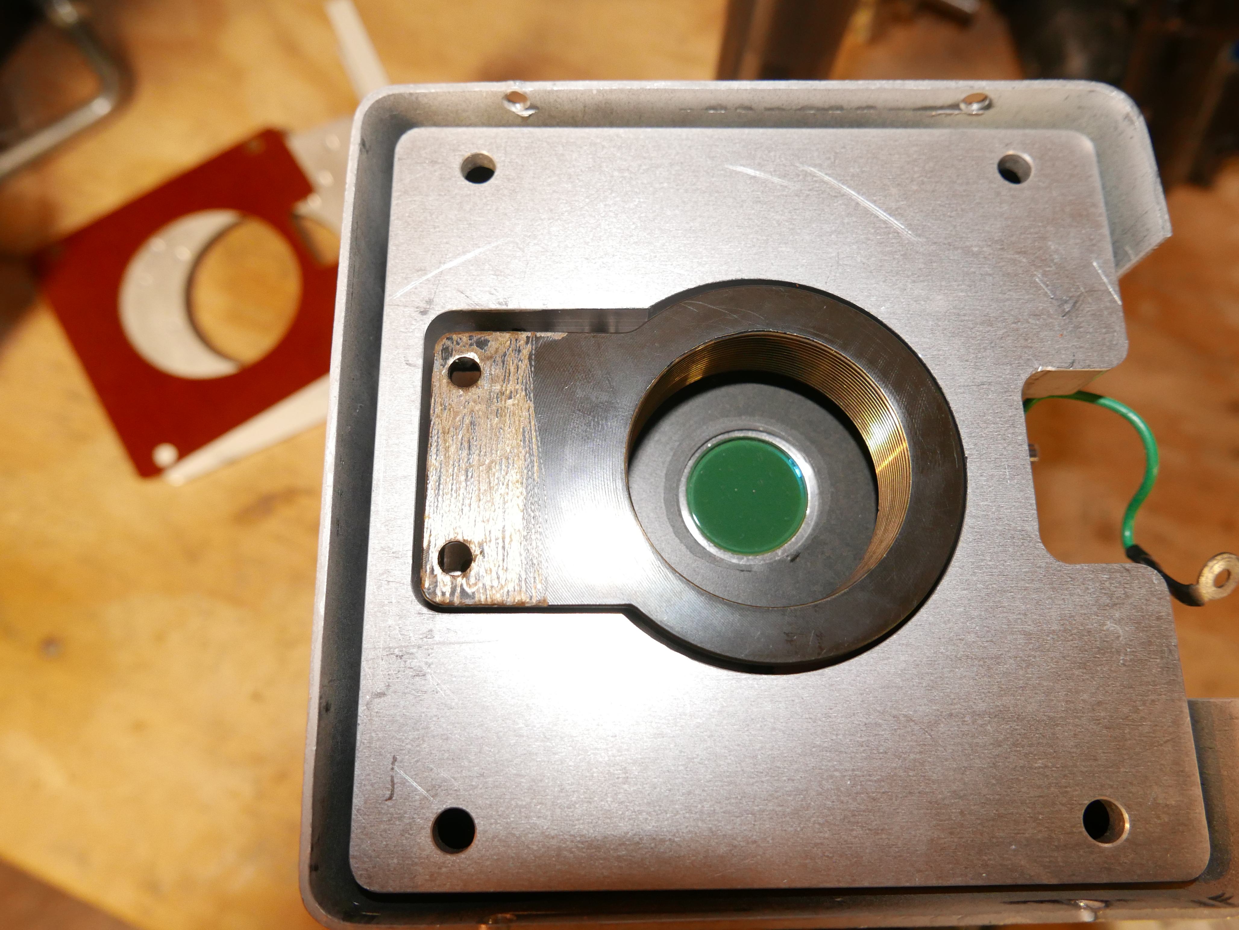
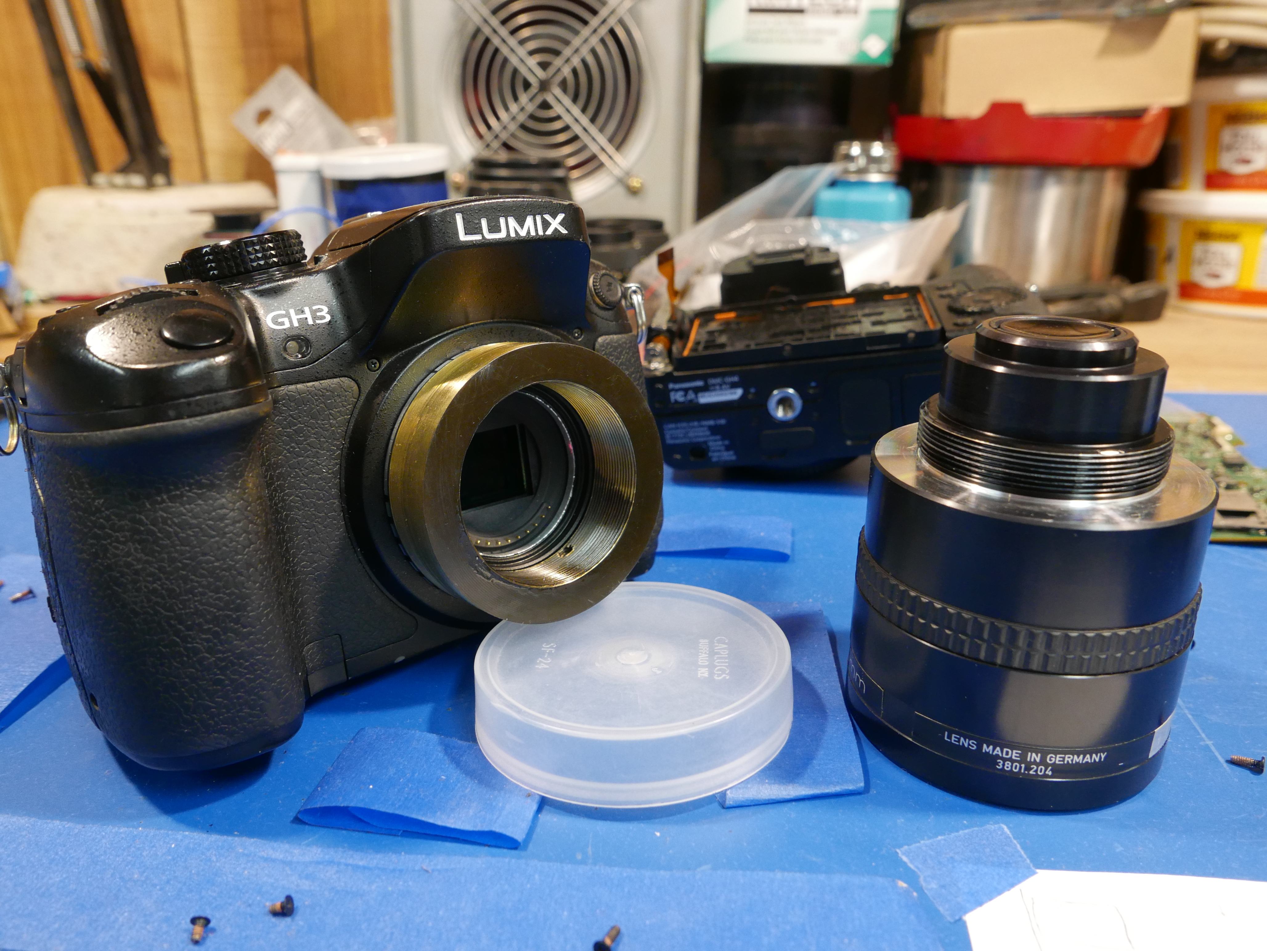
Luckily, these questions were not to difficult to answer. When I took apart the imaging camera, I noticed that the lens was very close to the green imaging sensor plane, almost touching it. I found it quite hard to get a good measurement of this distance, as it had to be assembled to get the measurement and I could not fit a tool in to measure. After rough testing the lens inside the GH3 Micro Four Thirds mount, I was convinced that I would be able to use the lens for its desired purpose: selective defocused shots. In other words awesome bokeh filled product highlight shots. The lack of a focus ring is a real bummer, and I decided to just use the threaded portion of the lens as a finite focus assist. I may decide to rehouse the lens at a later date and add a dedicated focus ring, but that is outside the capabilities of my machining equipment.
That leads me to the next answer: I decided to use a preexisting Micro Four Thirds mount and mount it to the mating threaded brass portion of the lens, that way I can keep the project as simple as possible and get to using the lens ASAP.
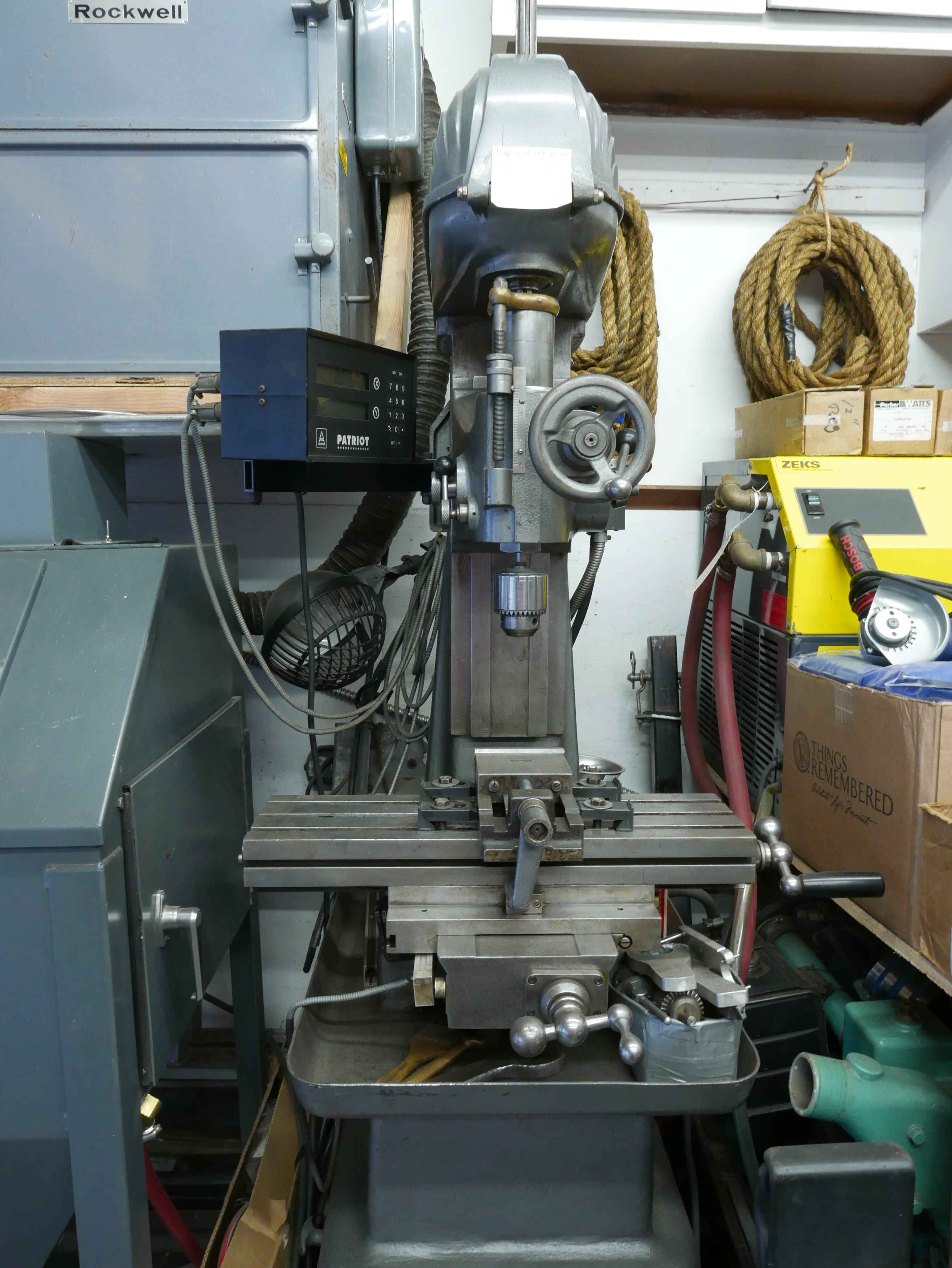
To make a dedicated lens mount you need to have a properly functioning lathe and a vertical mill with a small amount of runout. Unfortunately, my "vertical mill" is actually a jig borer, made in a time before time. The table is quite worn, and it would have produced an undesirable result in the threaded brass piece. Gosh, I can imagine the off center lens mount lobes now [shutters]. Ideally, if you have access to a CNC machine, lens mounts are easy as cake. So if you want to go to town on this, send away to have a CNC'ed Micro Four Thirds mount made.
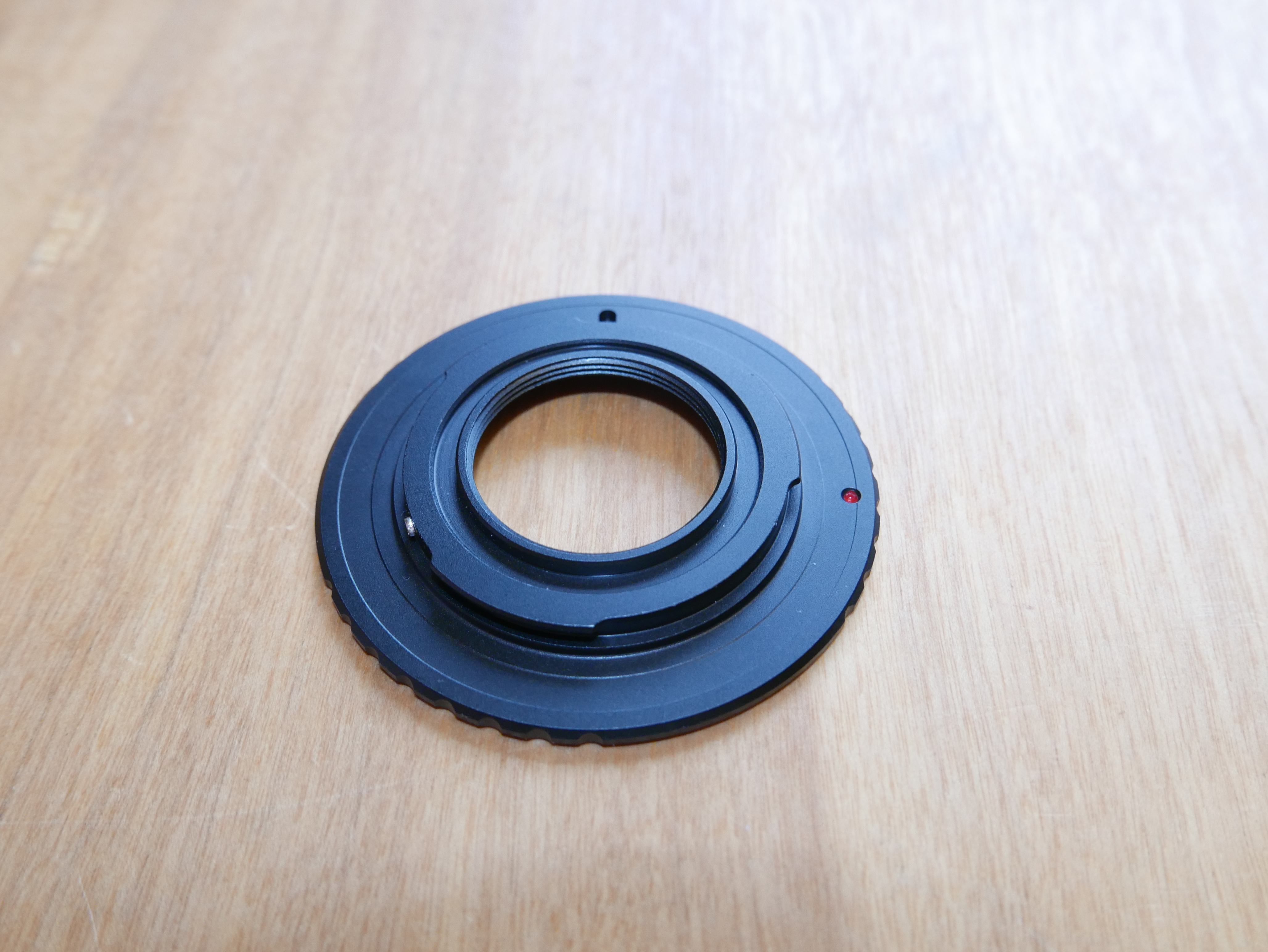
I went with the cheapest and simplest Micro Four Thirds mount available on the Internet: a C-mount to Micro Four Thirds adapter. Luckily, this adapter is literally the thickness of a Micro Four Thirds mount portion on a lens, and just features a small inner diameter circle with the thread pitch for c-mount lenses. These mounts are anywhere from $5-10 on amazon or ebay. They are about $1 USD on ebay china, so i went ahead and ordered a few for testing purposes. Surprisingly enough, the Micro Four Thirds c-mount adapters from china looked almost identical to the ones sold on amazon and through other retailers. Sure, they took a tad over a week and a half to my door (not bad bro) but I was in no rush to get ripped off.
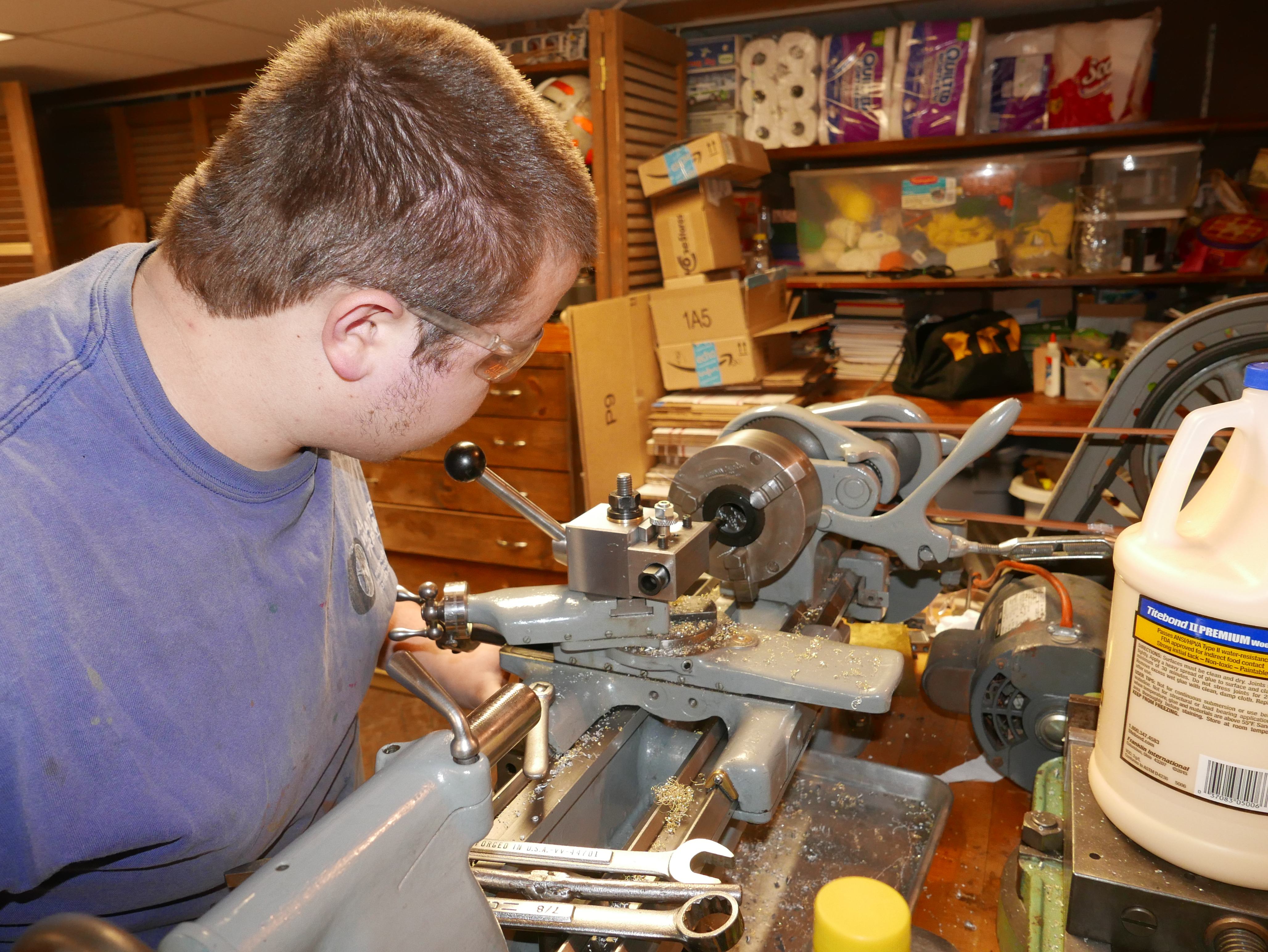
While waiting for the mount to arrive, I decided to focus my attention on cleaning up the brass mount. First up was to face off that lovely belt sanded side. Luckily, my brother acquired a South Bend lathe and some tooling last year, making this type of work easy.
Here's a nifty diagram for the South Bend lathe. Using a 4 jaw chuck and a dial indicator, I centered the brass mount in the axis of revolution. After about 20 thousandths off, I was satisfied with the surface quality, so I went ahead shifted my focus to the foot like portion of the brass mount.
I was originally going to keep it and thread a 1/4-20 tripod mount. Realizing the lens was not that heavy, I just decided to remove this geometry and have a fully concentric threaded brass mount for the lens. A bandsaw and a 3-jaw chuck installation later, I was ready to turn off the remaining unneeded exterior brass.
Before turning a diameter, it's an important preliminary step to remove a majority of the unneeded material if it is at all possible. Ideally, you want to avoid interrupted cuts, as it can wear your tooling erratically, and can cause premature carbide tip chipping. Remember, tungsten carbide is an extremely hard material, and can hold an edge very well, but it is also very brittle. Thus, it is important to avoid temporal changes in stress on your tooling.
The longer the interrupted cut, the more uneven the load placed on the tip edge, and the greater your chances of ruining your tooling. By reducing excess material, you can smoothly remove that excess diameter without hiccup.
Since I wanted to turn the entirety of the outside diameter, I could not use the exterior of the part as a mount face in the chuck. In this case, the inner diameter was used as a mounting face for the 3 jaw chuck, and brass shims were used to protect the threads from marring. The 3 jaw chuck allows for quick centering of a part as they are inherently self-centering (the three individual jaws are adjusted simultaneously on a scroll gear, and move when you rotate the chuck key on the chuck). Sure, three jaw chucks are less precise than 4 jaw chucks, but they can be more convenient to use in a pinch.
The South Bend makes quick work of brass turning. At this point, I think the world needs more GIF machining sequences, so I'm just gonna keep pumping em out. Nah, this is the last one.
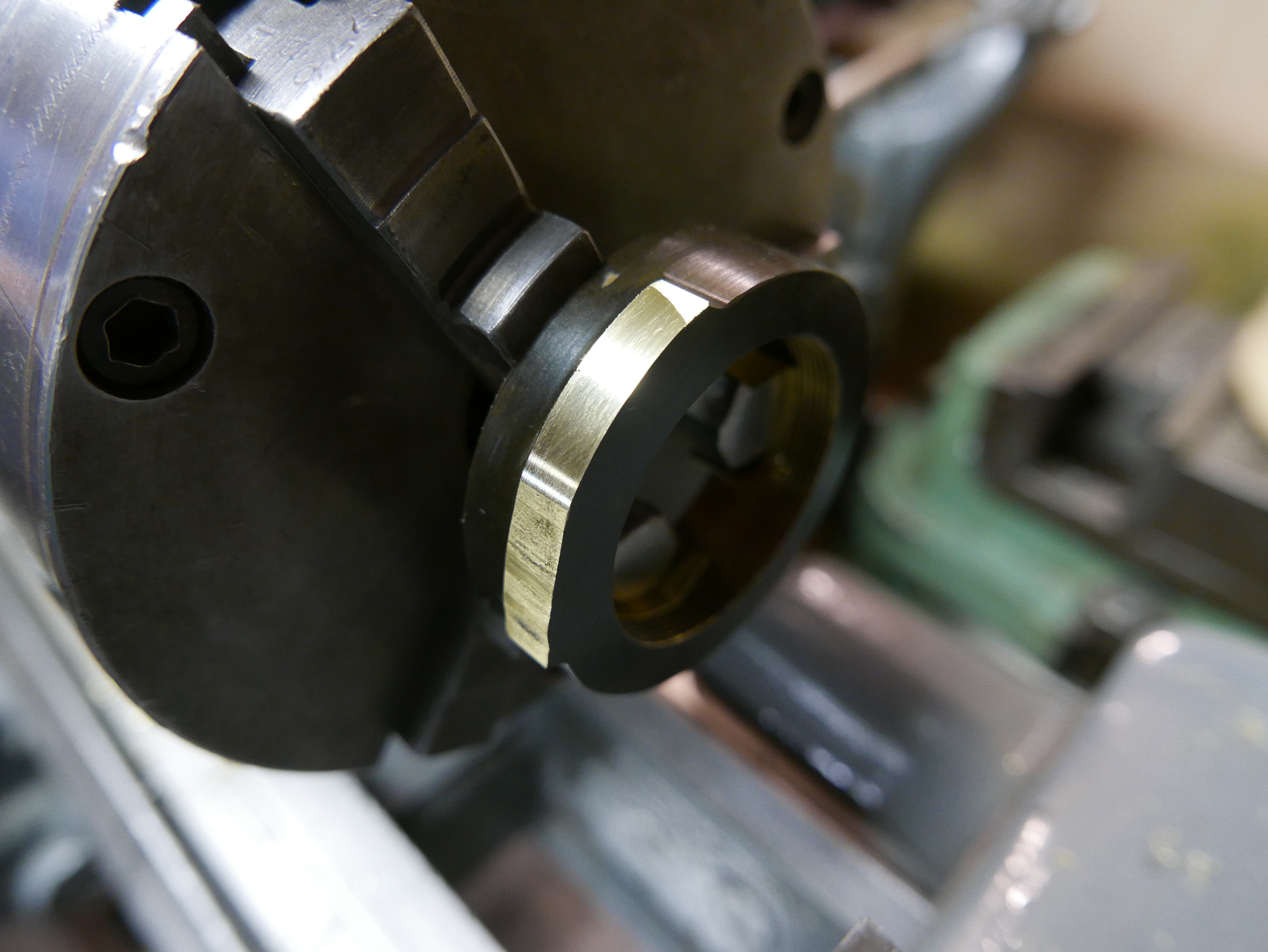
With the part faced and turned, it was time for a quick fit. After some quick lubrication with 3-in-1 oil, the brass turned onto the lens fluidly. There was a bit of trouble turning the brass piece onto the lens from the faced off side, so I opted to just thread the brass piece to the lens from the other side.
That isometric view sure looks good on it. During the machining process I was sure to keep the lens away from the lathe at all times to prevent destroying the optical surfaces.
Next up was to remove the inside material from the c mount lens adapter. A quick adjustment on the 3 jaw chuck, a rotation of the tool post and a mounting of the boring bar later, the c mount adapter was minus the c-mount part.
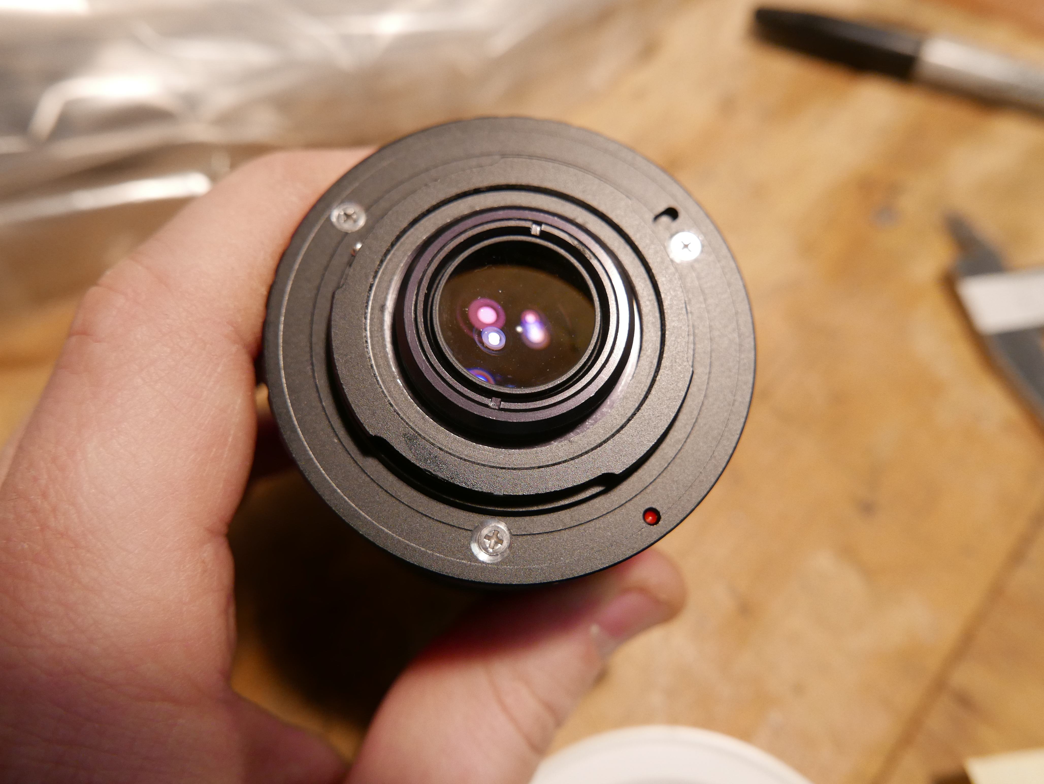
Another quick fit. The last most part of the lens was able to fit through the center of the Micro Four Thirds mount, so I thought that was an adequate amount of material removed.
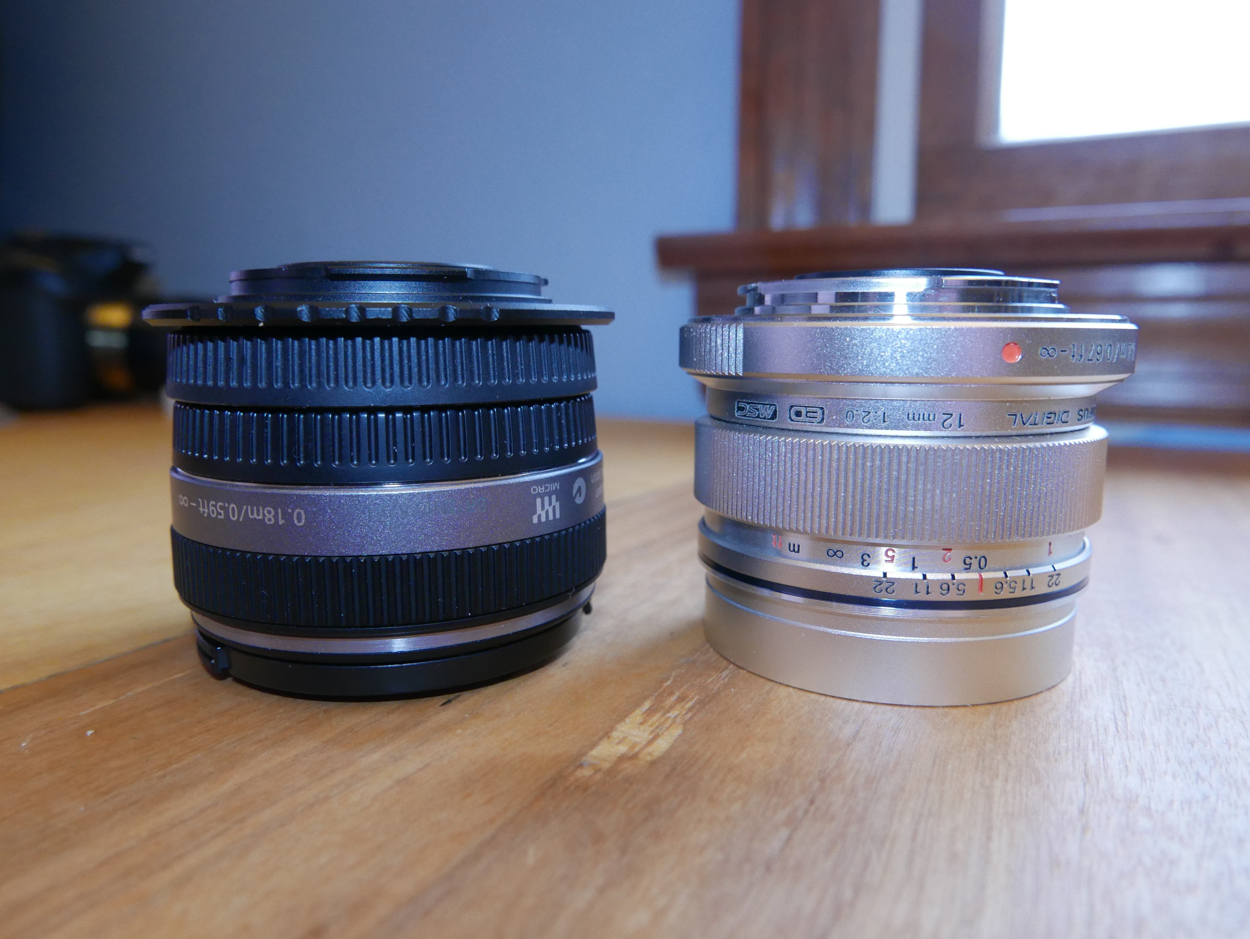
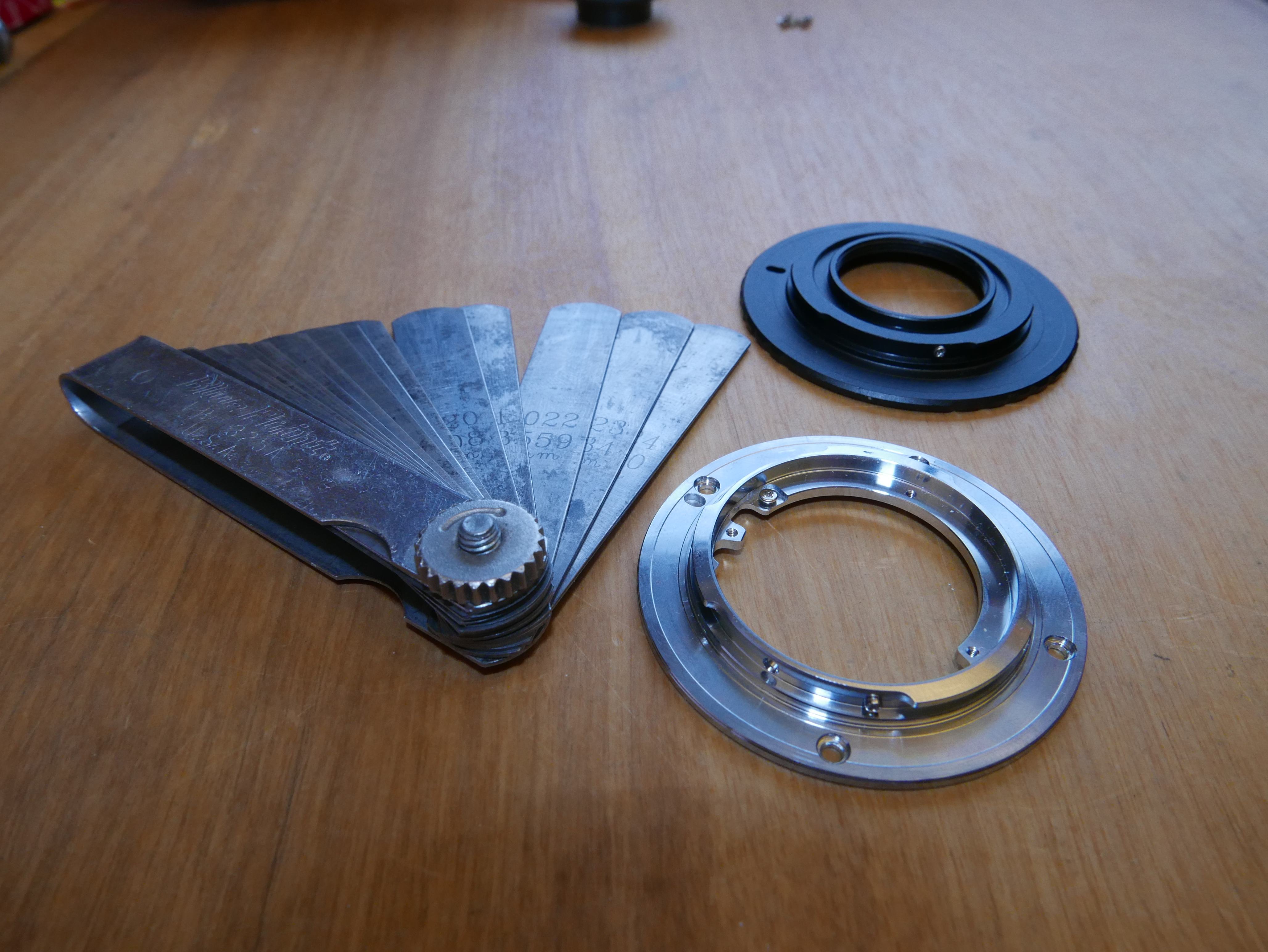
What am I doing now? Well, I needed a reference hole pattern to mark onto the micro four thirds mount adapter. Seeing that the Micro Four Thirds mount has 3 lobes, I saw it fit to use a triangular hole pattern to avoid any interference with the mount lobes during final assembly. What do you know, the 20mm f1.7 and 14mm f2.5 Lumix lens both feature a 3 hole pattern Micro Four Thirds mount. So I disassembled a 14mm f2.5 lens and used it as a template for the hole centers on the other micro four thirds mount.

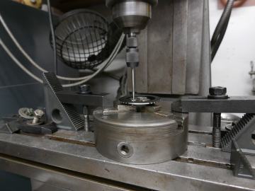
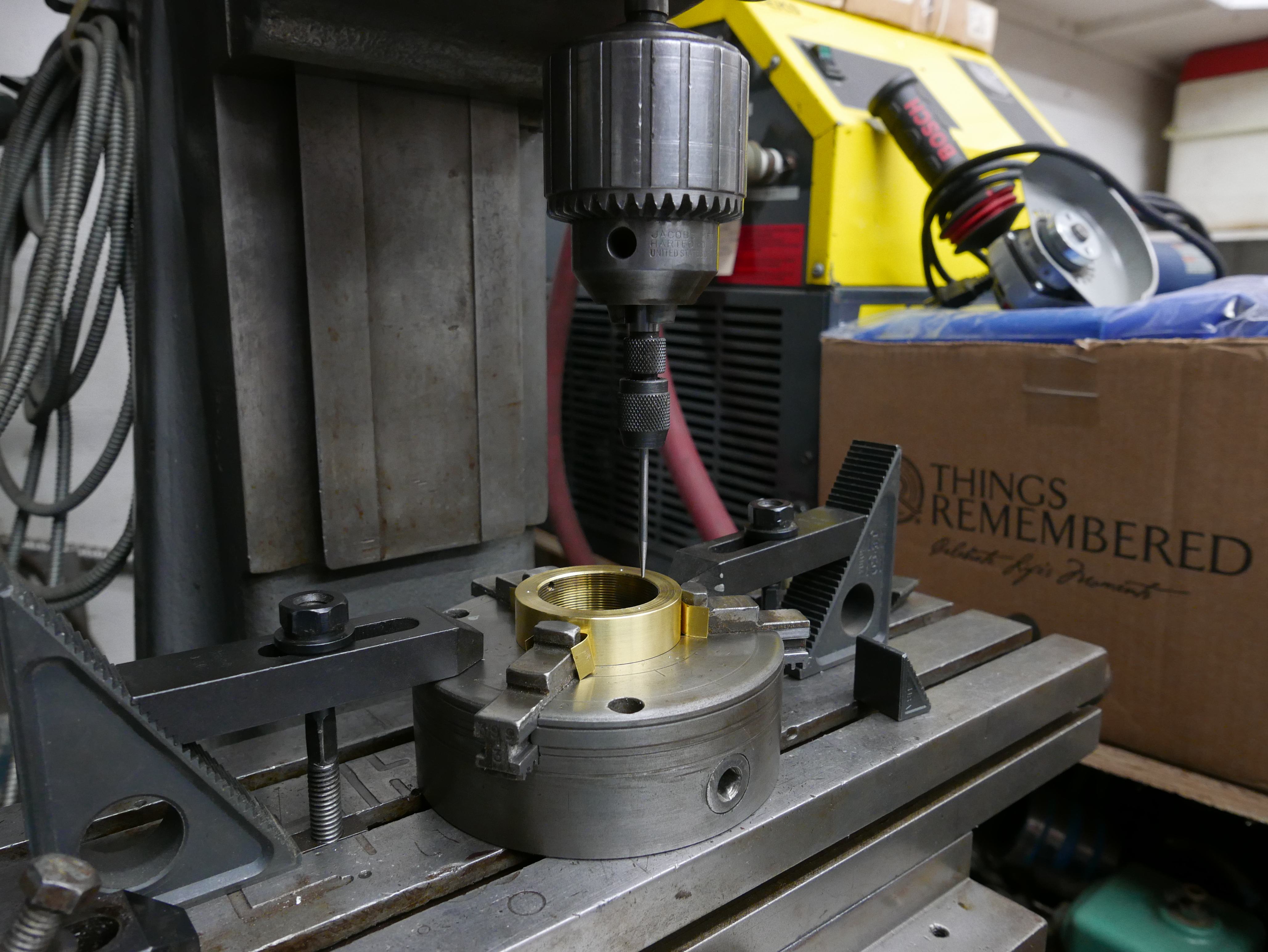
I took the part out of the chuck and removed the chuck from the lathe. The chuck was then used as a vise, and mounted to the Sheldon Vernon jig borer table with T-blocks and stepped blocks. These stepped blocks are pretty neat and feature a receding tooth pattern, so the part cannot slip when an axial torque is placed on the bolt holding the block to the table.
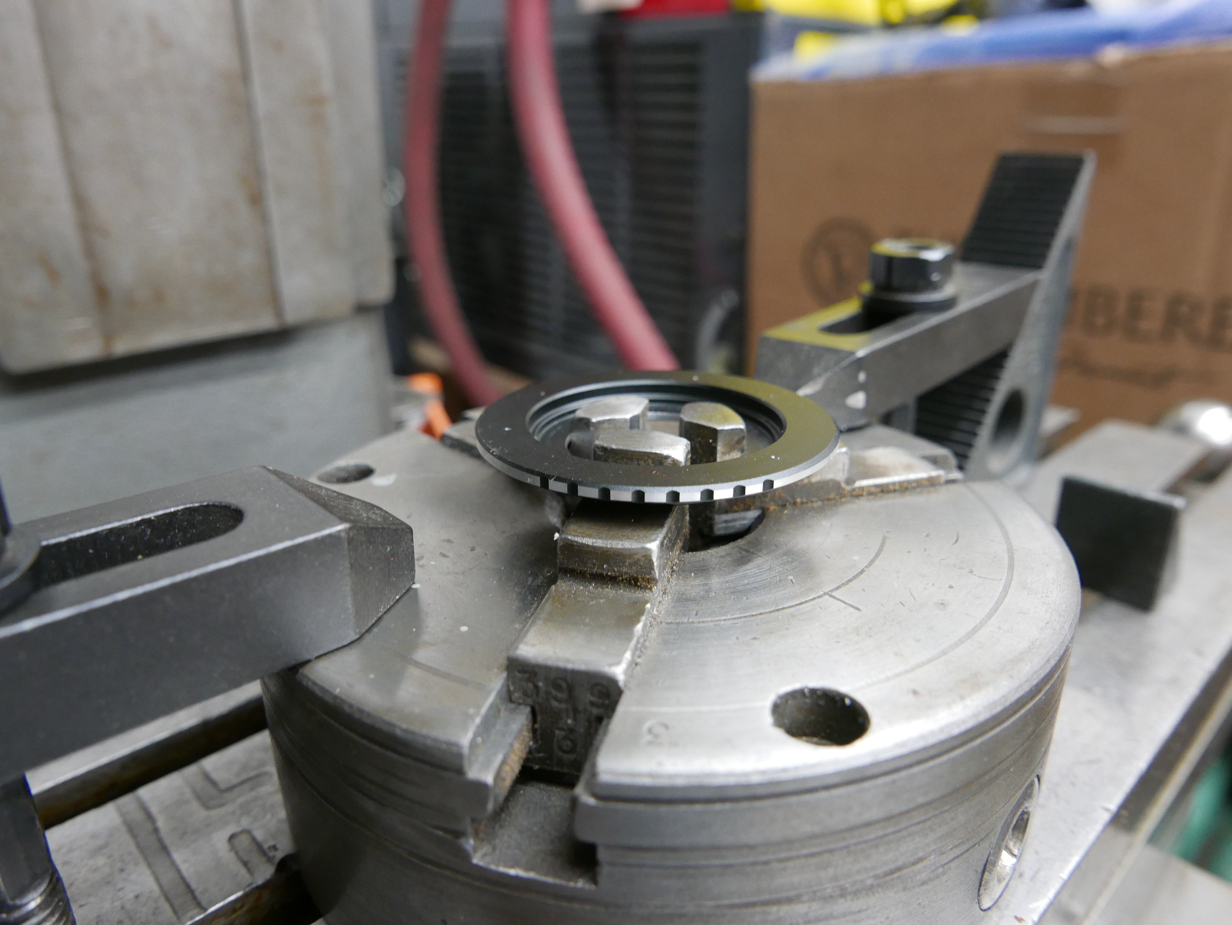
Close up on the table setup. I marked out the holes in the exact same pattern that the 14mm lumix lens had and then used a spring loaded center punch to leave indents into the surface.
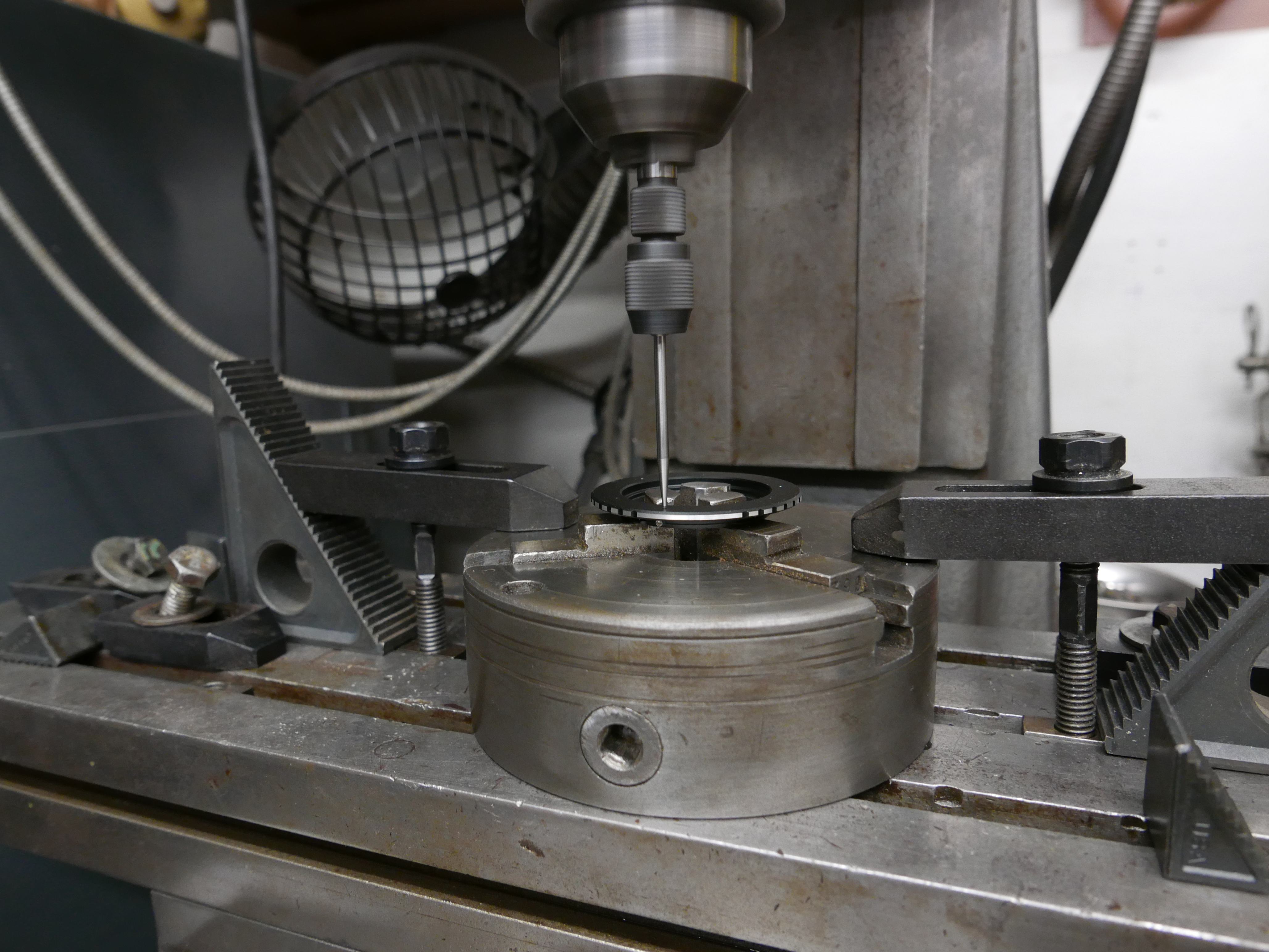
Why the hell would you want indents on a lens mount surface? Well, for one, it allows you to use a wiggler to find the exact center of the hole you want and line that up with the quill on the jig borer, making your drilled hole precisely accurate. Yes, wiggler is the correct name for a machinists' tool.
You see that? That's more than just convenience. It makes your end result a hell of a lot better than just blindly drilling a hole with a drill press or power drill.
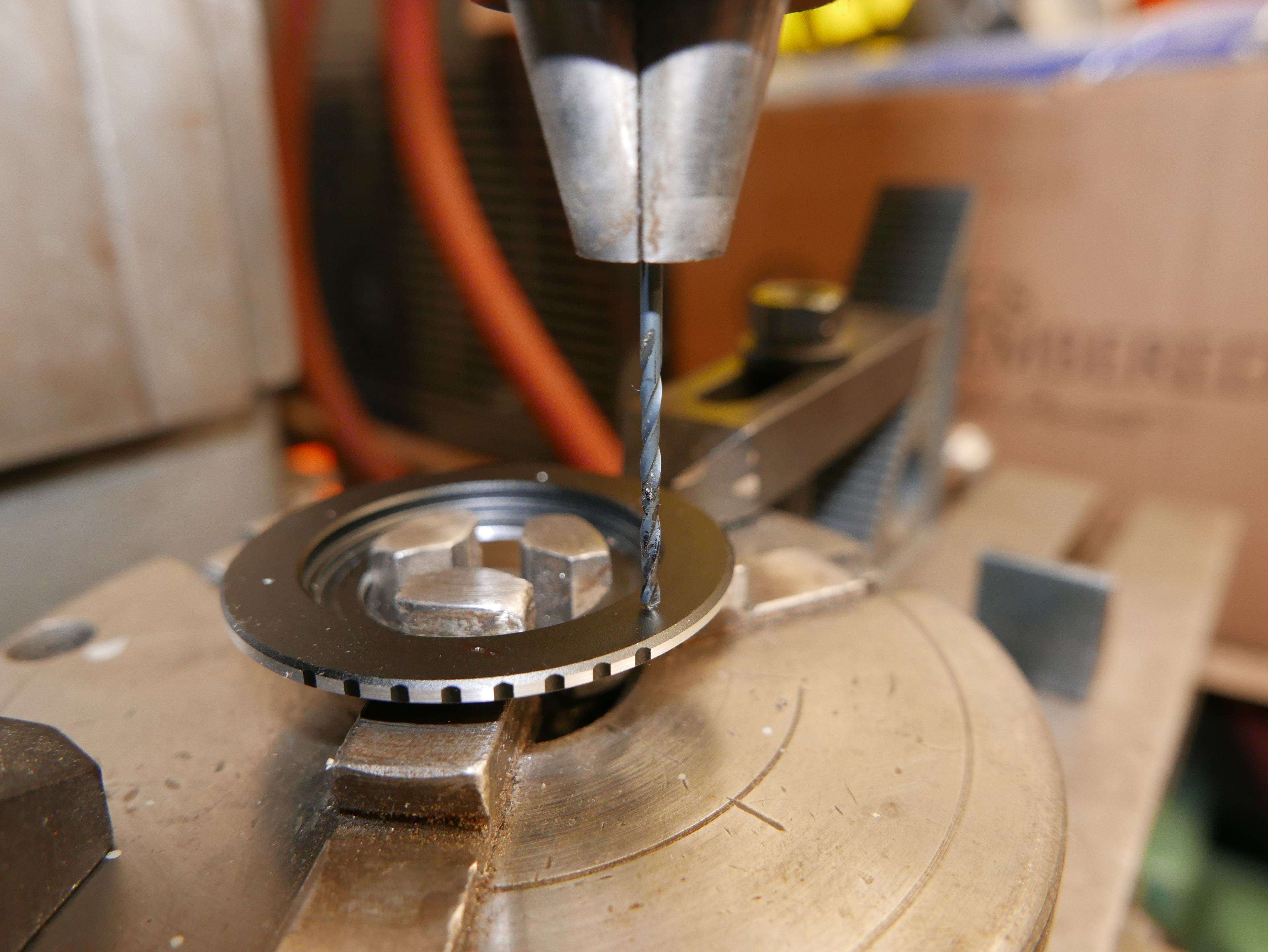
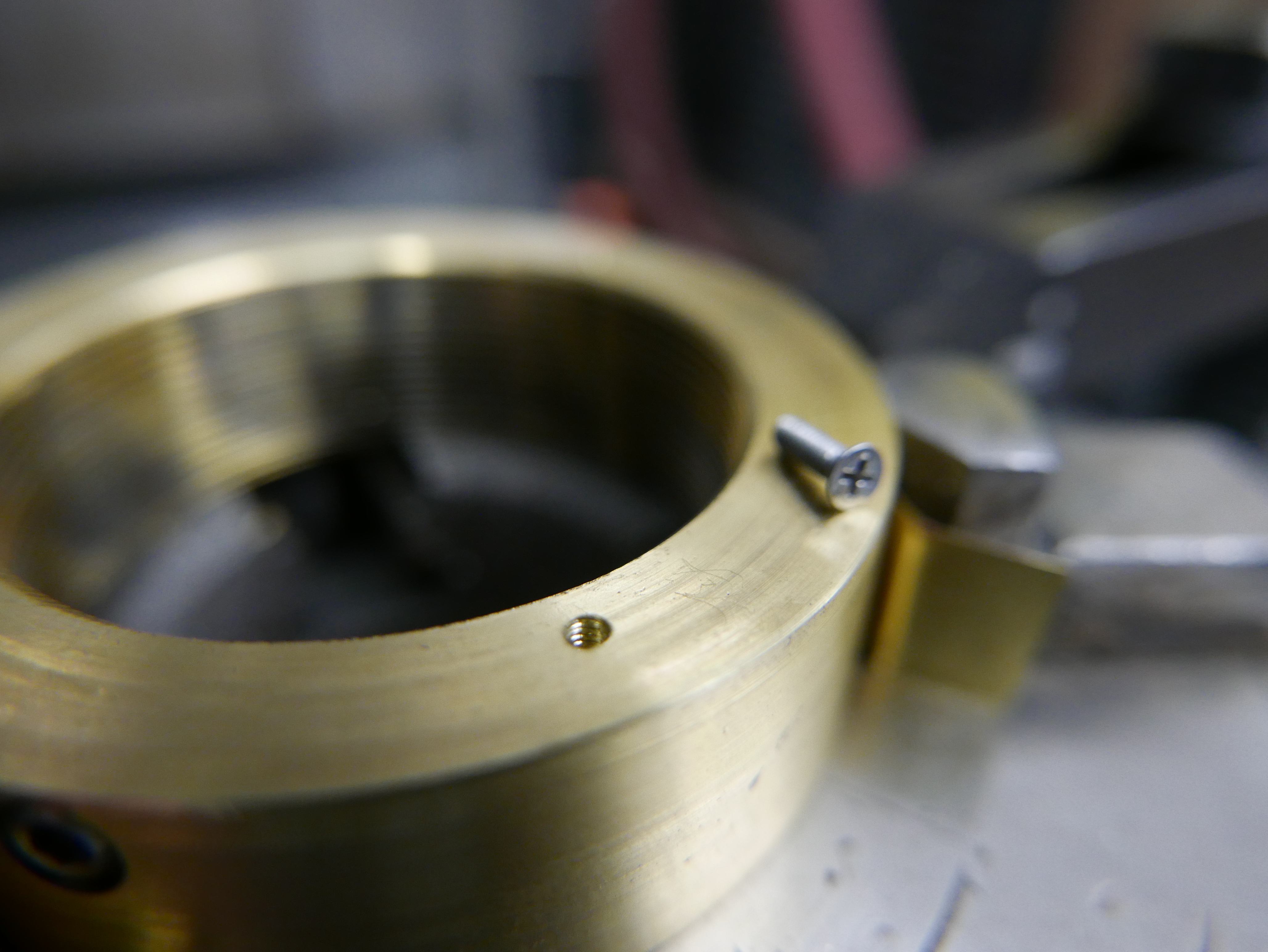
I used that same hole pattern from the mount as a template again, and marked appropriately onto the brass. This is where the threaded screw holes would be in order to mate the Micro Four Thirds mount to the brass adapter. Again, the wiggler was used to find the true center of the hole to ease drilling.
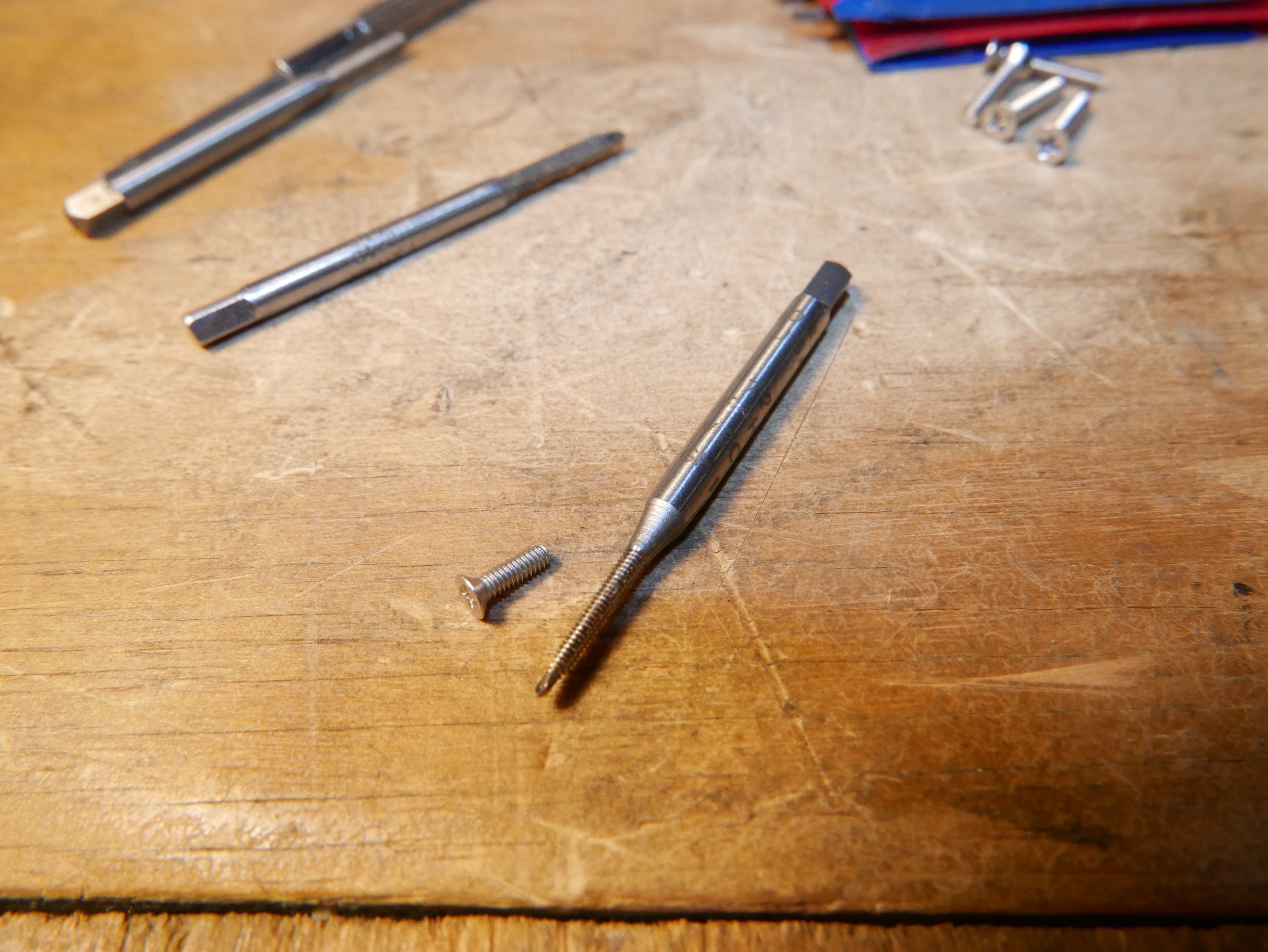
As for screws, I decided to go with 1-72 (size 1 screw, 72 threads per inch) Phillips machine screws with a "flat head" or chamfer under the head, so they sit flush inside countersunk holes. This is important because you do not want your screw heads interfering with the mating surfaces of the lens mounts. This will destroy the mounts and the screws. I used the appropriate 1-72 tap and a 1/16 drill bit to make the threaded holes. How did I know what tap and diameter hole I would need? I'M GLAD YOU ASKED! I used a drill and tap table. Yup. That simple
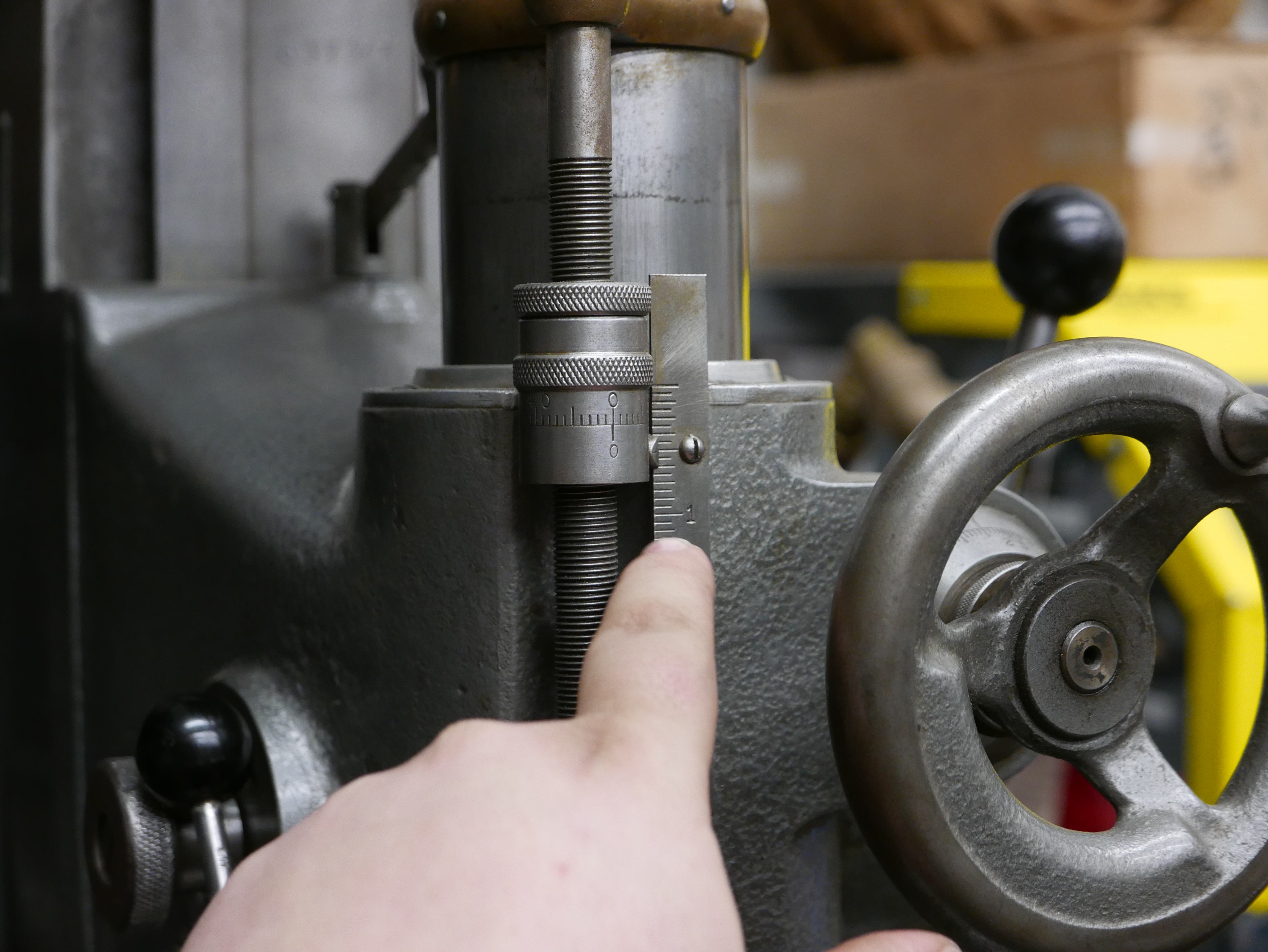
Using the depth gauge on the jig borer quill, I was able to keep the hole depth consistent, and I intentionally drilled deeper than necessary to provide additional room for the tip of the tap. This is generally good practice, so you avoid breaking your tap and get the full length of thread that you desire.
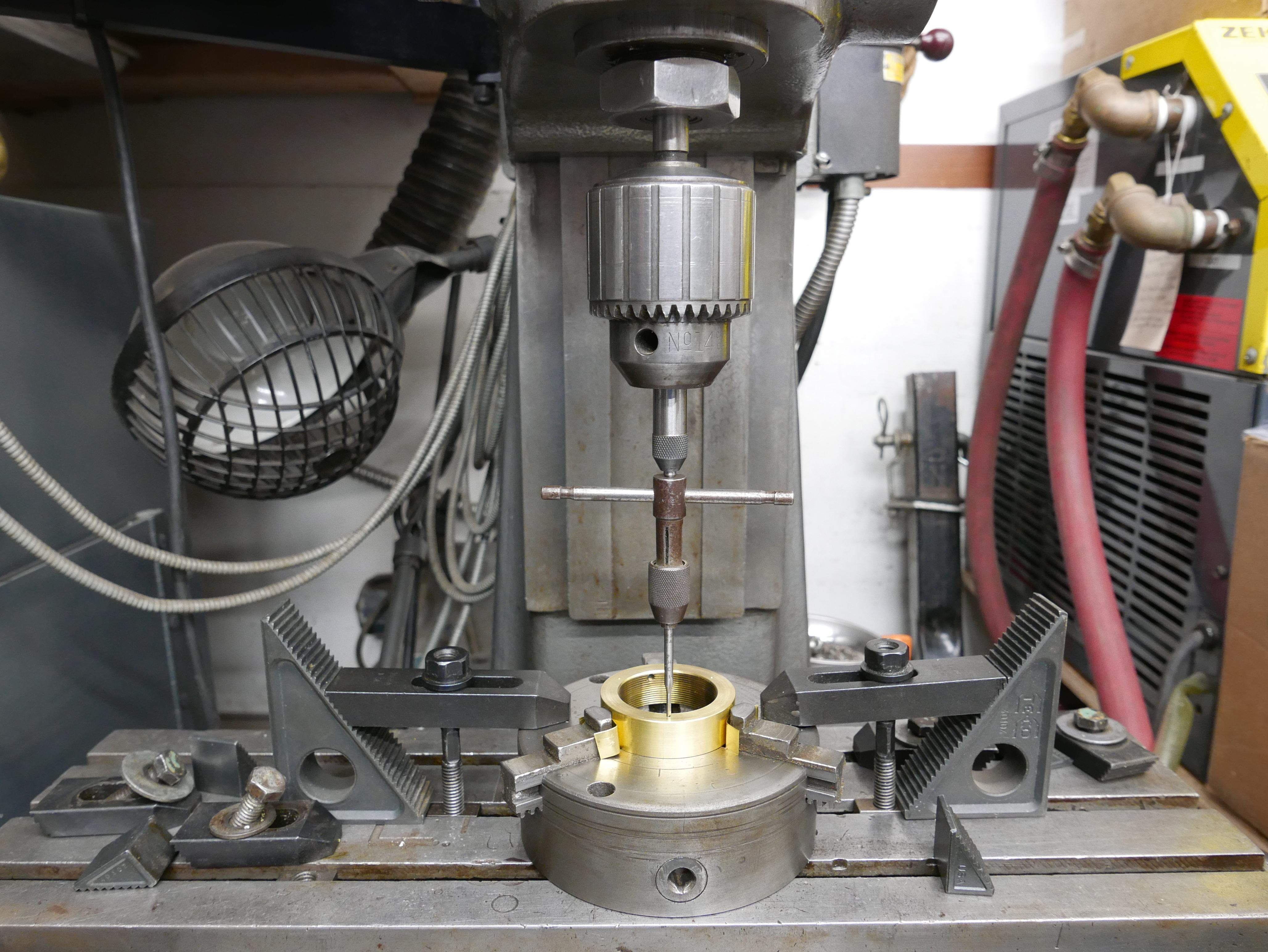
Tapping is pretty simple. Or is it? It is very simple to do wrong. In this case, a spring loaded tap follower was used to both center the tap handle and provide guidance for tap depth in the hole. Some benefits of using a spring loaded tap follower are that it leaves the tap handle in suspension, keeps the tap handle perfectly orthogonal with the work surface and keeps the tap concentric with the drilled hole. Oh and it keeps track of the tap depth. How awesome is that?
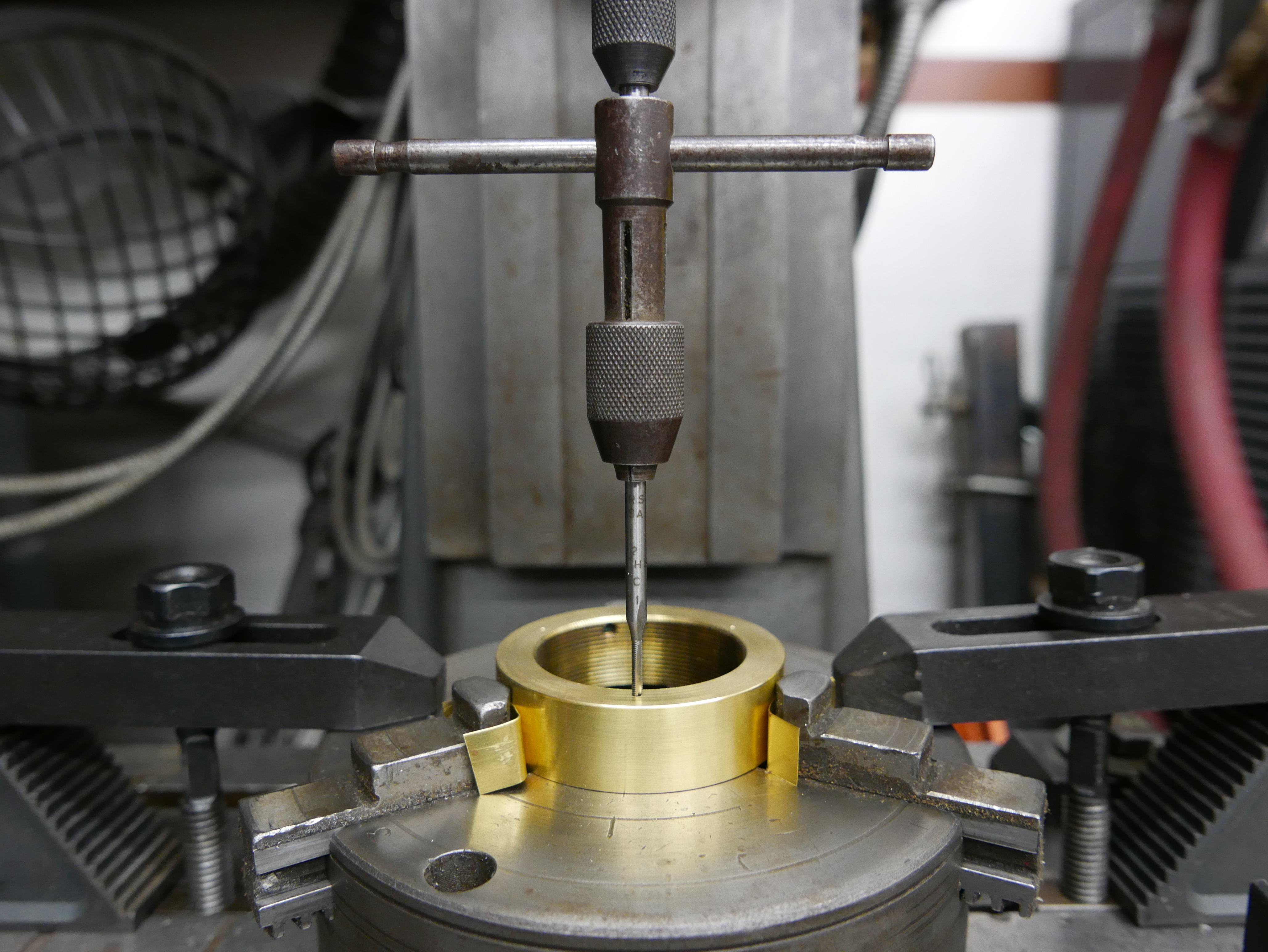
Look at how awesome that is. This brass deserves to be tapped. Notice that brass shims were used here again to protect the surface of the brass part. #Sacrificialmaterial.
But Anthony, I just torque on the thing and finish it up quick right? It's just tapping? NO. You don't even need to put effort into turning the tap, it should be that well aligned. There needs to be sermons about spring loaded tap followers. #preach.
Assembly was straightforward enough, but I was noticing on initial testing that my center of focus was pretty poor on the lens. I found that the rear lens element could not recede far enough into the camera mount because the physical camera mount was in the way. Ideally, the rear element of the lens should be as close to the Micro Four Thirds sensor as possible (as was in the imaging camera) so a plunge cut was necessary to allow for the rear element housing to pass through the center of the Micro Four Thirds mount.
Back to the lathe it went. After placing the Micro Four Thirds mount in the three jaw chuck, I swapped in a boring bar in my tool post, adjusted the tool post to be parallel to the part and left the carriage at a 27.5 degree angle offset. This allows for the appropriate angle to remove material from the inside face of a part.
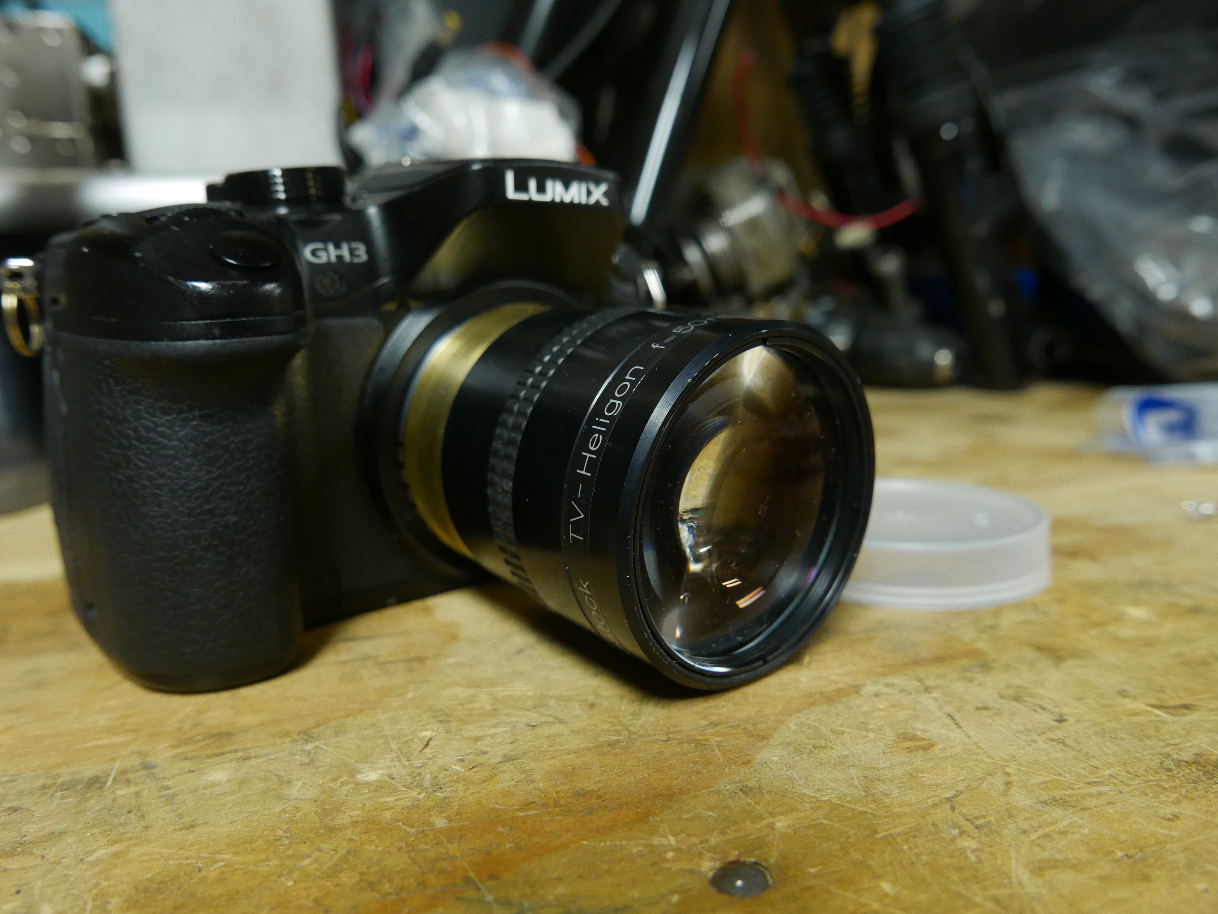
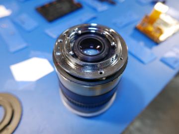
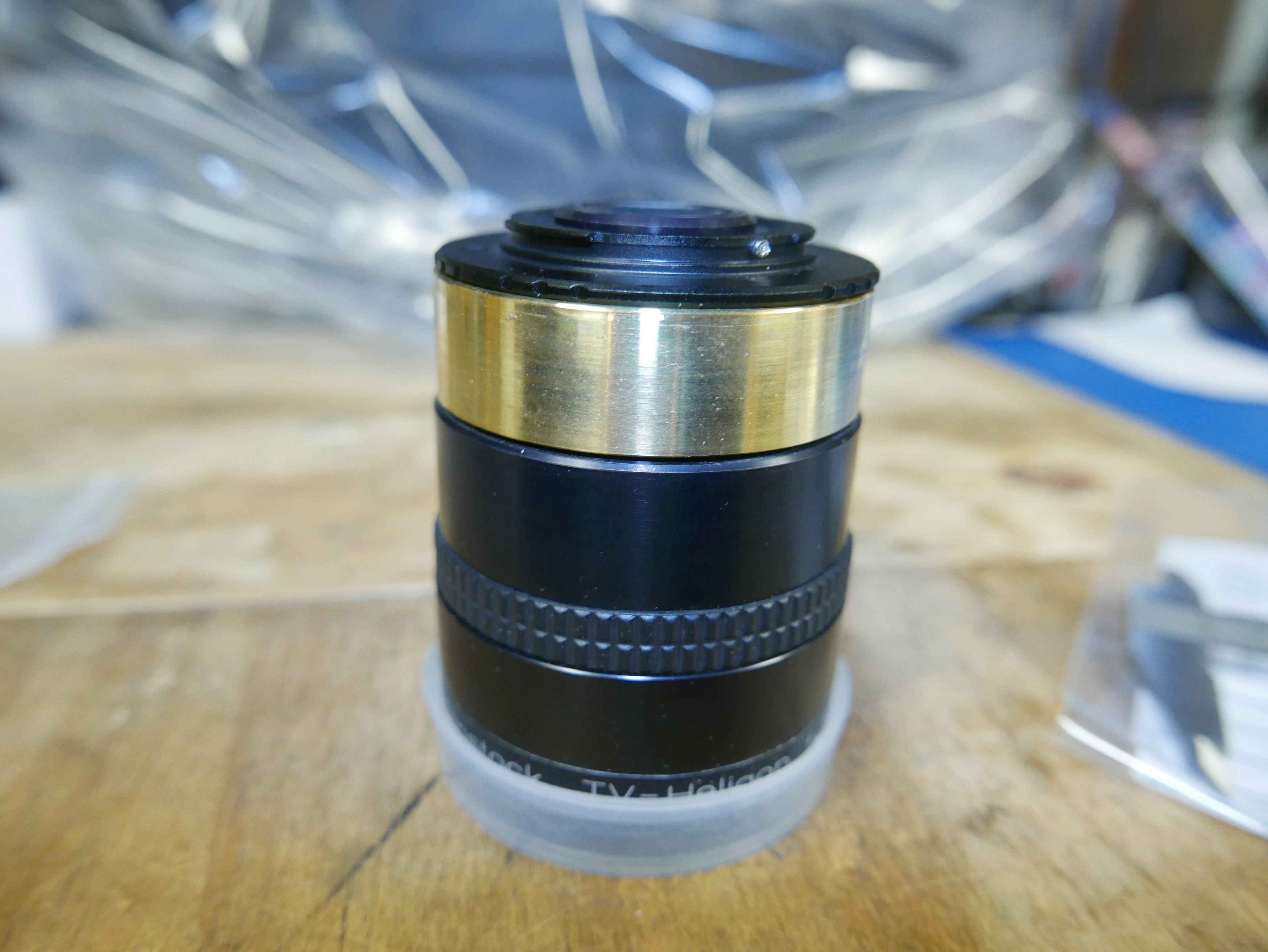
With the material removed and some quick final assembly, the lens was ready to be put through its paces. Here's the final result of my labor of love. I decided to keep the brass spacer flush with the exterior surface of the lens to give it a more uniform appearance.
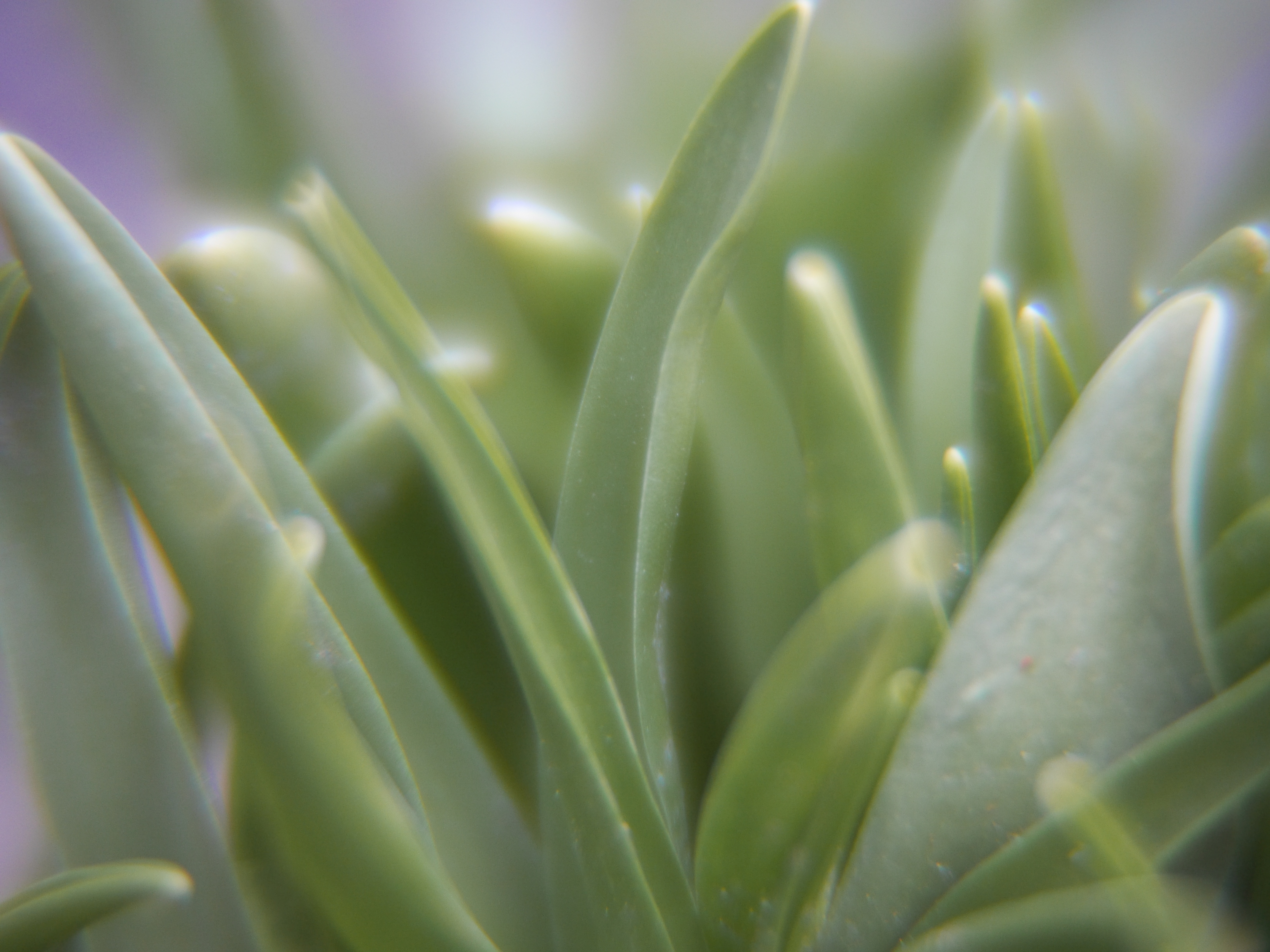
Here's some rough test footage. You'll find this lens throws light around in whimsical fashions. It is crazy how wicked small the depth of field is on this lens. It feels like just 1 inch in diameter is in focus at all times. Nuts. After that lens exercise I now see that I will need a gimbal and a whole lot of patience if I want to redo some of these shots.
Important Notes For Small Shallow Depth of Field Lenses & Final Results
DONT USE AUTO WHITE BALANCE! I have done some tests, and indeed it seems that AWB gets confused on what is truly white and washes out your images. This is an example image with AWB on:

Here's an example image with AWB off:
See the huge difference? The color is more accurate with AWB off, and there is less of a washed out appearance. I have a feeling this washed out / gray appearance is what some flickr users were encountering, and they thought it was the lens. I believe there is a good chance they made this same mistake I did initially. For reference, all these test shots contain the original EXIF data so when you click on the full size image, so you can confirm this issue.
Unfortunately, I did not know this when shooting the sample video, so the color in the video may not be truly accurate. I also used the wrong shutter angle in a few shots, so there's that issue as well.
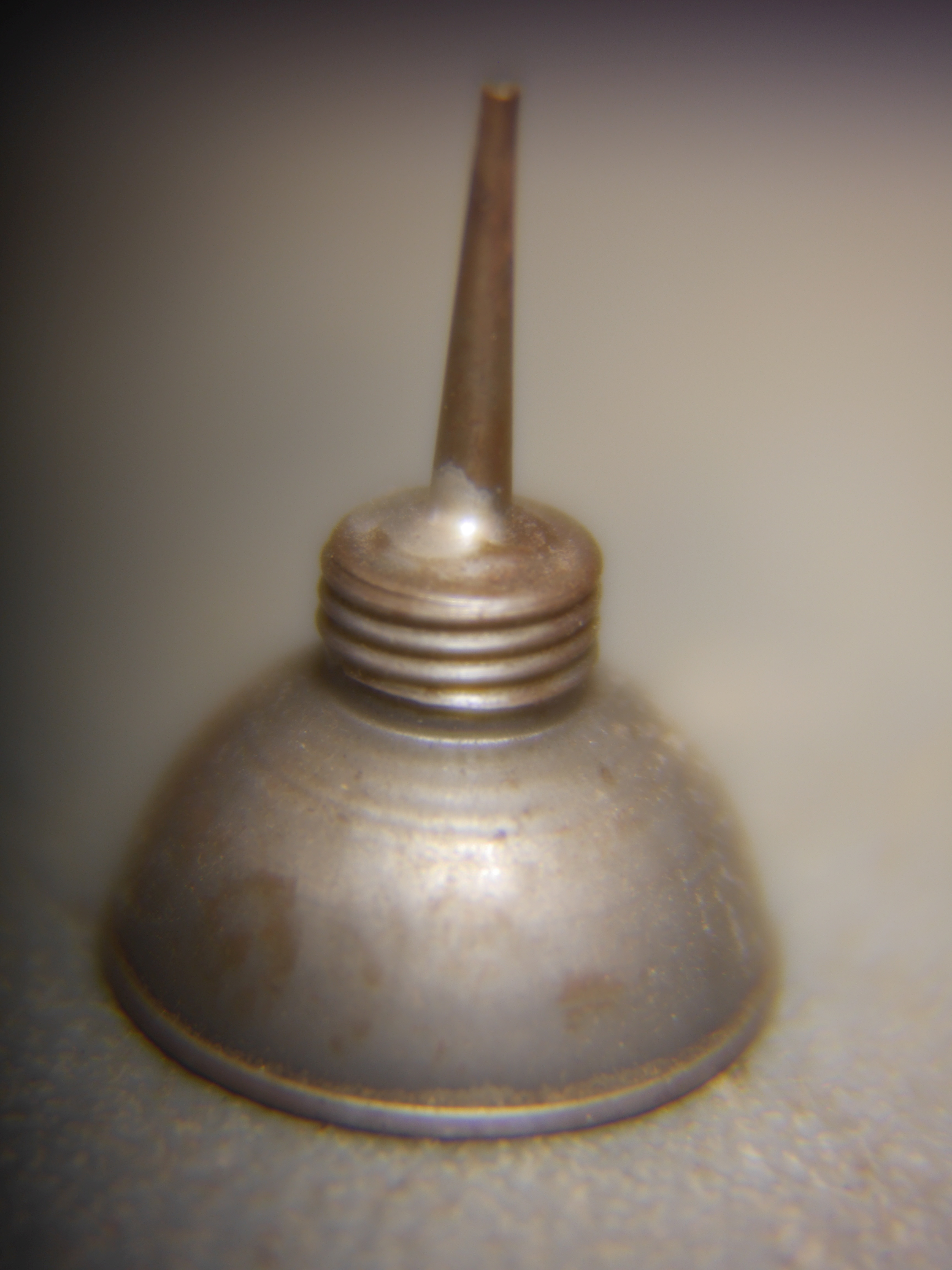
This is another example of where AWB truly falls apart. The foreground is a very tiny oil dropper. The background, believe it or not, was the top of my dryer, which is incredibly white. Yes, the image is not perfectly in focus, but this lens is not yet capable of being perfectly in focus without further modification.
Regardless, you can see how the tiny depth of field is tricking the camera into thinking the foreground and background colors are close, when in fact the oil dropper is a silver-gray and my dryer is, you guessed it, white.

To get good results, I used "daylight" setting on the DMC-GH3 instead of AWB, and I was pretty satisfied with the result. I did not use "natural", "vivid" or "scenery" picture profiles either, I just used the standard color profile included with the Lumix cameras. Also, I did not notice anything ajar in regard to the image when I scrubbed through the halogen and color temp modes. These photos represent a more true representation of the color rendition of this lens.

What does this say about AWB? For one, that it is so damn good at setting the reference white in an image that we almost entirely rely on it as a species to compose photos. I usually swap around from AWB to daylight and incandescent modes frequently - but that's the only reason why I caught it. If i was an infrequent user, this totes would have passed me by.
Why did this happen? For one, it could be the image processing engine interprets whites based on edge detection, and the results of the kernel convolutions are resulting in values that are not as distinct as it usually encounters, and are closer to the original kernel components. So the camera thinks the out-of-focus areas are more white than they are, and in turn puts a gray tone on output images, making color rendition incorrect.
Is it bad that AWB is broken for these type of lenses? NO. NOT AT ALL. This lens perfectly represents a worst case scenario that no one would waste time accounting for because there are no lenses of this nature designed for micro four thirds. Also, if you have a lens as quirky as this, you better be using all full manual controls anyway. I bet other camera systems would have similar if not the exact same issues on AWB.
Future Improvements
I can get the rear lens element closer to the sensor if I face off more of the brass threaded shim. This should decrease the depth of field to something more practical, and finally allow the lens to achieve accurate focus with the sensor. As it is, the lens is focusing slightly in front of the sensor, making razor sharp images impossible. In its current state, the lens is quite hard to use for any shot. I'll update this post when I get access to a lathe that is more suitable for threading. Sorry South Bend, I just don't think you're up to rethreading the brass mount.
Now that I'm talking about improvements, I feel kind of sad that I spent the time to make this adapter and used a shitty mount. There is something to be said about these cheap adapters though. They are inexpensive and easy to acquire, but at the end of the day, they are pretty poorly made. Sure you can get a "neewer" or "fotasy" or some other name adapter, but at the end of the day, these are just labels. They are almost all re-brands of products produced from the same molds on the same machinery in hidden low cost manufacturing houses scattered across the 4 corners of the globe.
What is most frustrating is what I like calling equivalence. These inexpensive adapters are made from the cheapest aluminum or magnesium alloy that's left over, and machined to the wrong dimensions. You will often find reviews of owners complaining of slop in the mount and lack of focus at infinity. BING BING BING! Poor machining.
In all fairness, camera manufacturers do not make the lens mount dimensions of either mating gender known. It has to be found out. This is frankly absurd and I am tired of this "walled garden" approach to business and manufacturing. Granted, I do not have to sign an EULA to buy or use a camera (I'M LOOKING AT YOU, EVERY SOFTWARE MANUFACTURER), but come on, just give us the mount CAD so we can play in our infinite sandbox.
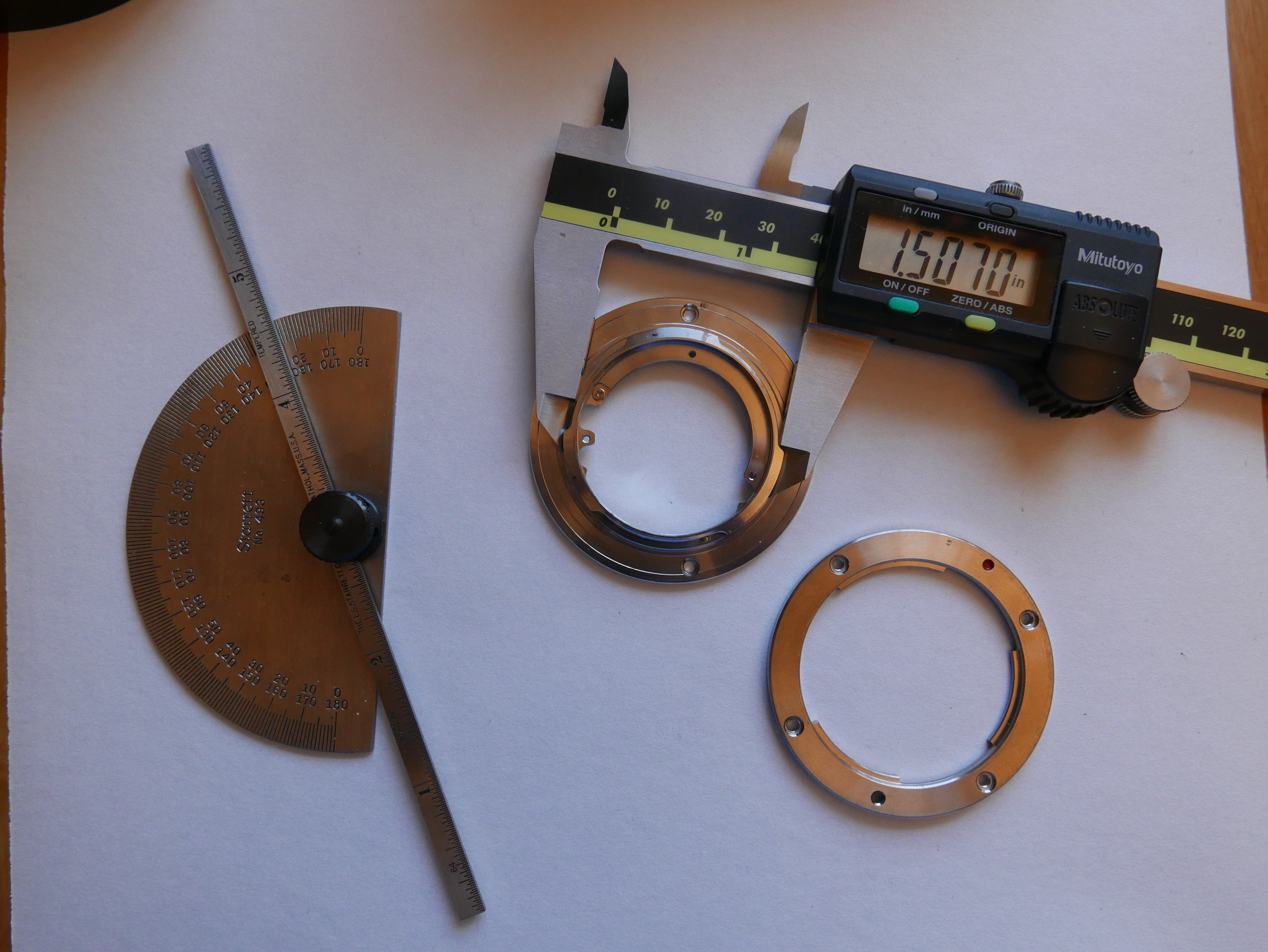
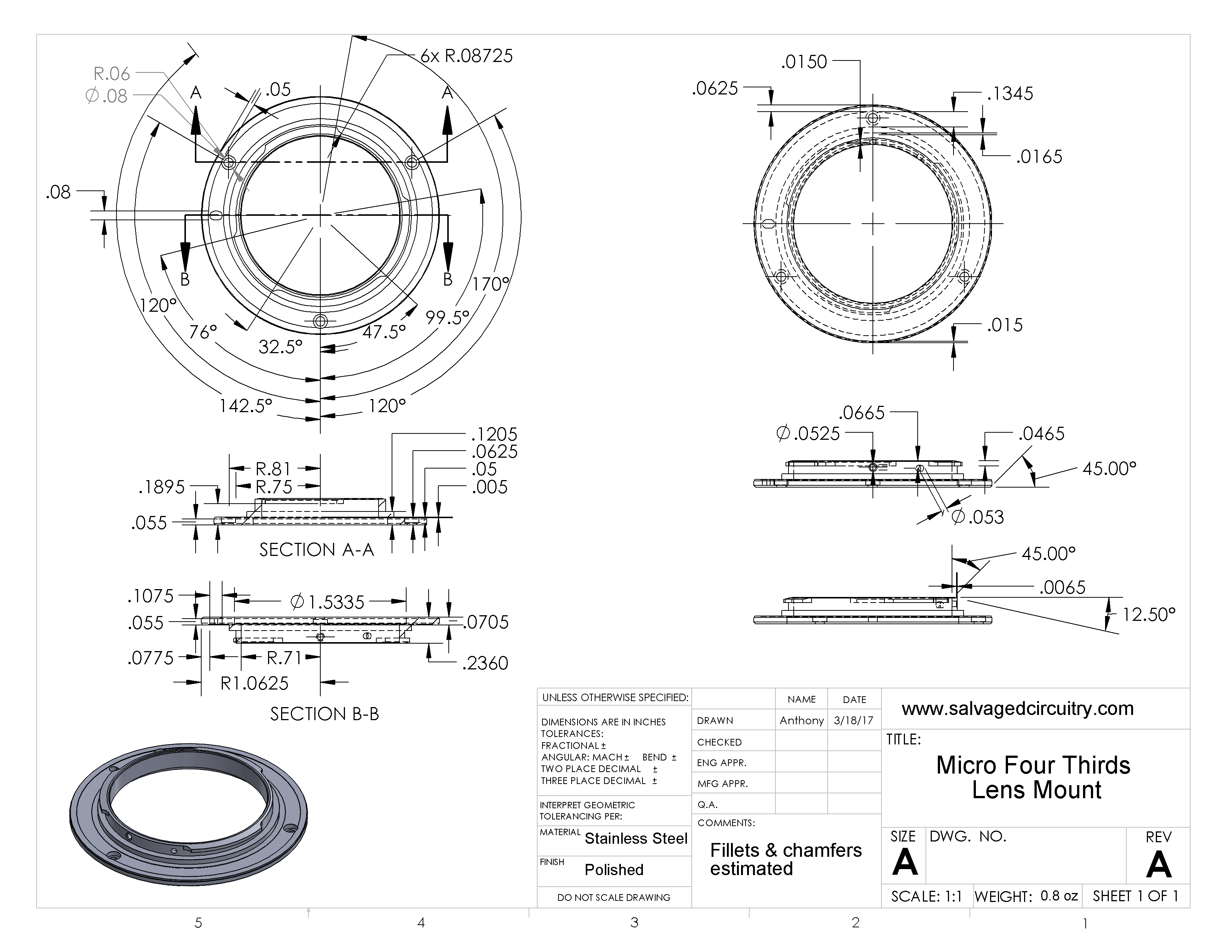
As you can imagine, I'm a bit flustered over this. So, I decided to do something about it. This is to all you creatives out there: Here is a CAD model of the standard Micro Four Thirds lens mount. This is the male portion of the mount that is attached to the rear of a Micro Four Thirds lens. Dimensions were taken from the lumix G Vario 45-200mm f4-5.6 lens mount, measured by myself and my trusty 4 decimal Mitutoyo caliper. The CAD was composed in Solidworks 2013. There are STL and IGS files available. The render was composed in Keyshot. The CAD files are available below and from Grabcad as well.
Micro Four Thirds Lens Mount CAD:
How Crazy am I? There are the technical drawings as well! So if you find an old school machinist whose better than using 1s and 0s, you're still covered. There are mechanical drawings in each zip file, and are also included on Grabcad. There were a lot of very fine dimensions and the spacing of dimensions on the 11x14 drawing space was quite limited. Forgive me, there are only so many 0.1in chamfers that can fit on a page ^_^.
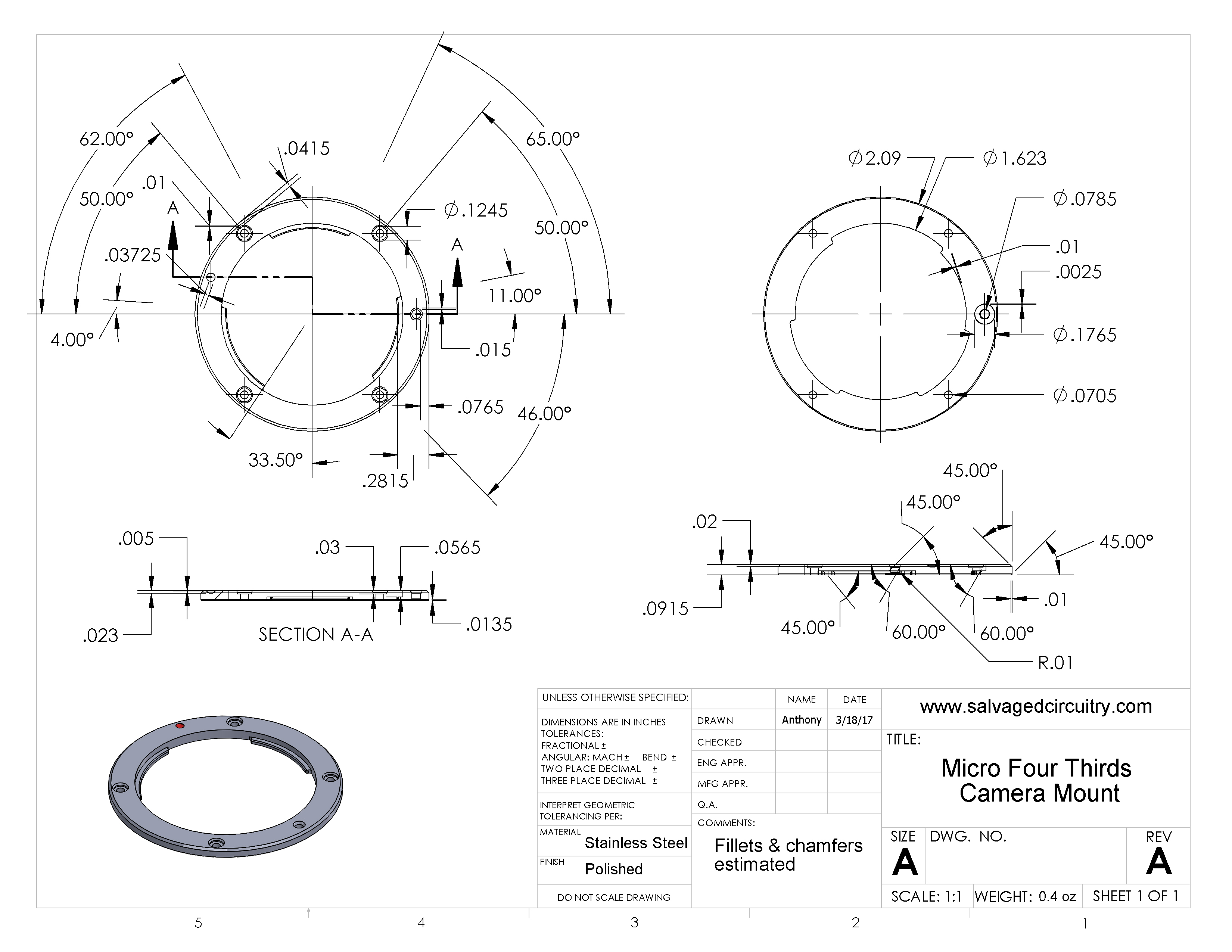
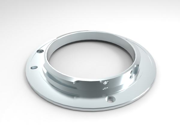
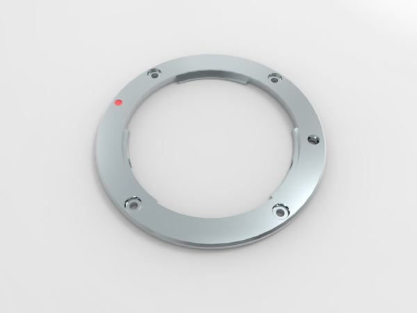
What's this? More? You think I'd leave you hanging homie? Here is the mating Micro Four Thirds camera mount, measured with the same caliper, to the same tolerances, available for download in Solidworks, IGS, Step, and technical drawing. Just like above, render done in Keyshot. The CAD files are available below and from Grabcad as well.
Micro Four Thirds Camera Mount CAD:
How did I get these measurements? Was there some magical fairy who came to me one night and whispered in my ear? did I have inside information from the Guardians of Mount Making®?
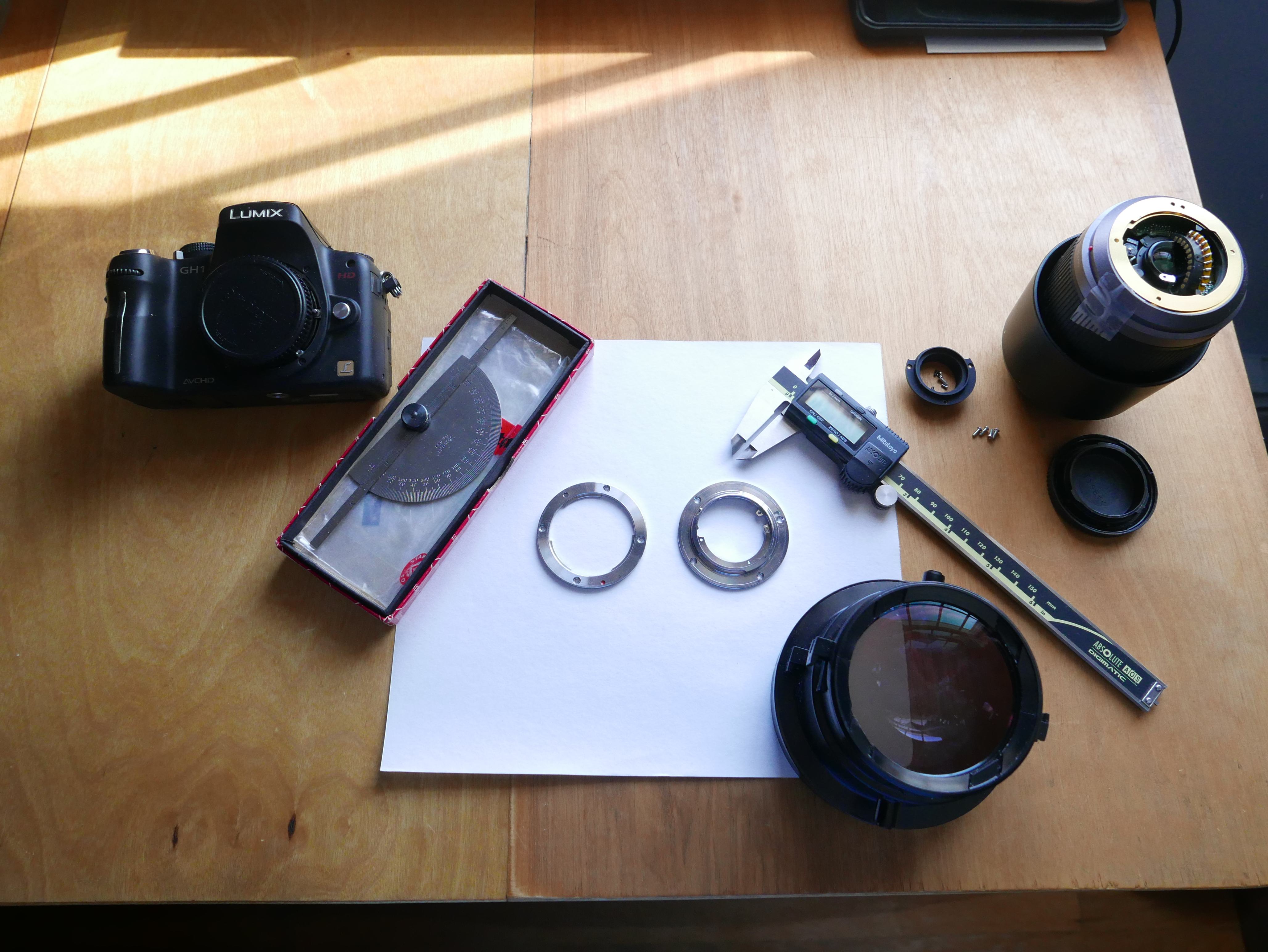
No, I used a Protractor, caliper, optical assistance, reference cameras and wit.
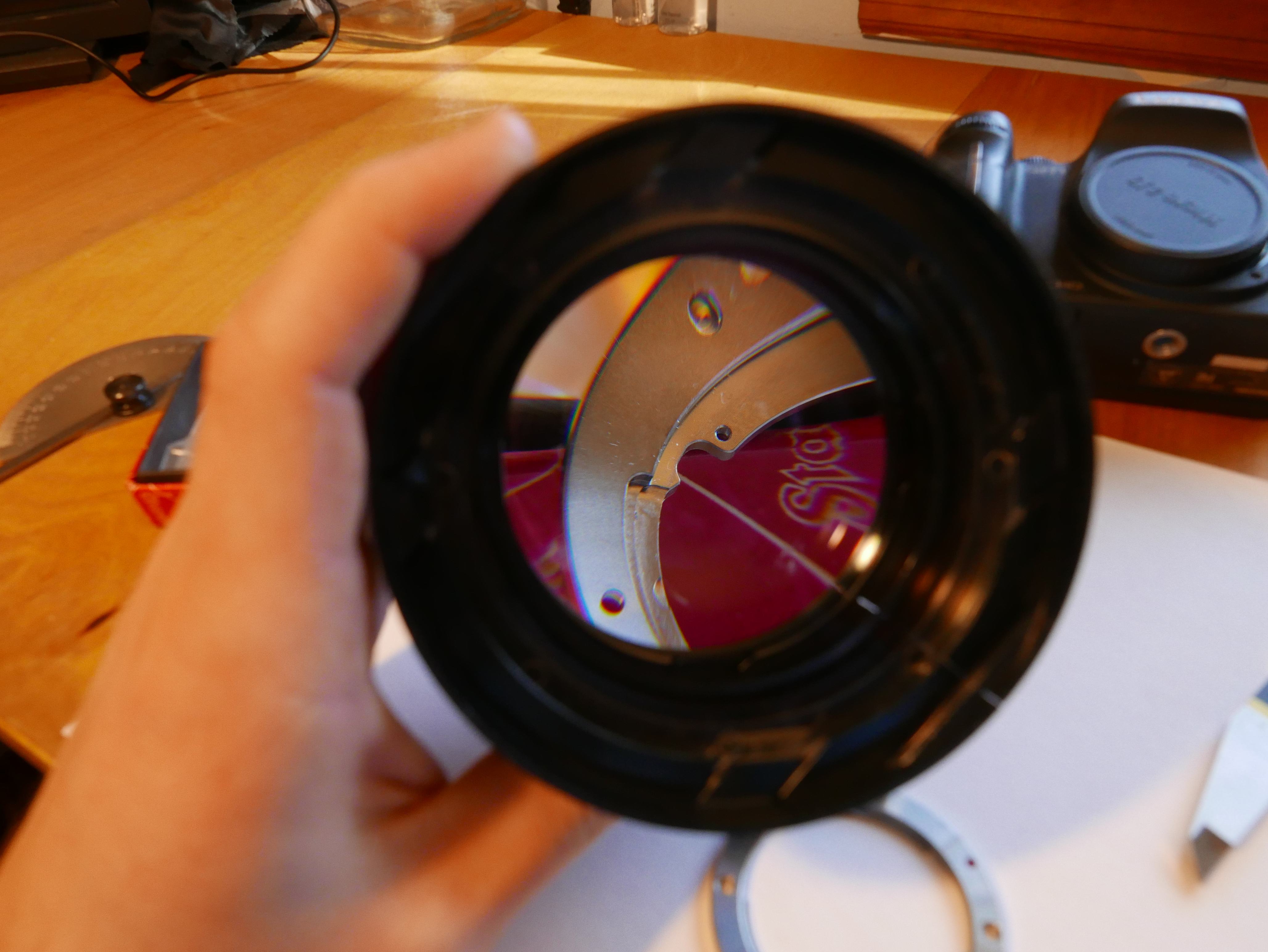
In case you were curious, that optical device is a lens set from a rear projection tv. Where can you get 3 sets of lenses that resolve 4x4in screens for free? That's right. Thank me next time there's one at the curb. Oh and that happens to be how I found out about those .1in chamfers and other extremely tiny geometry on the micro four thirds mount.
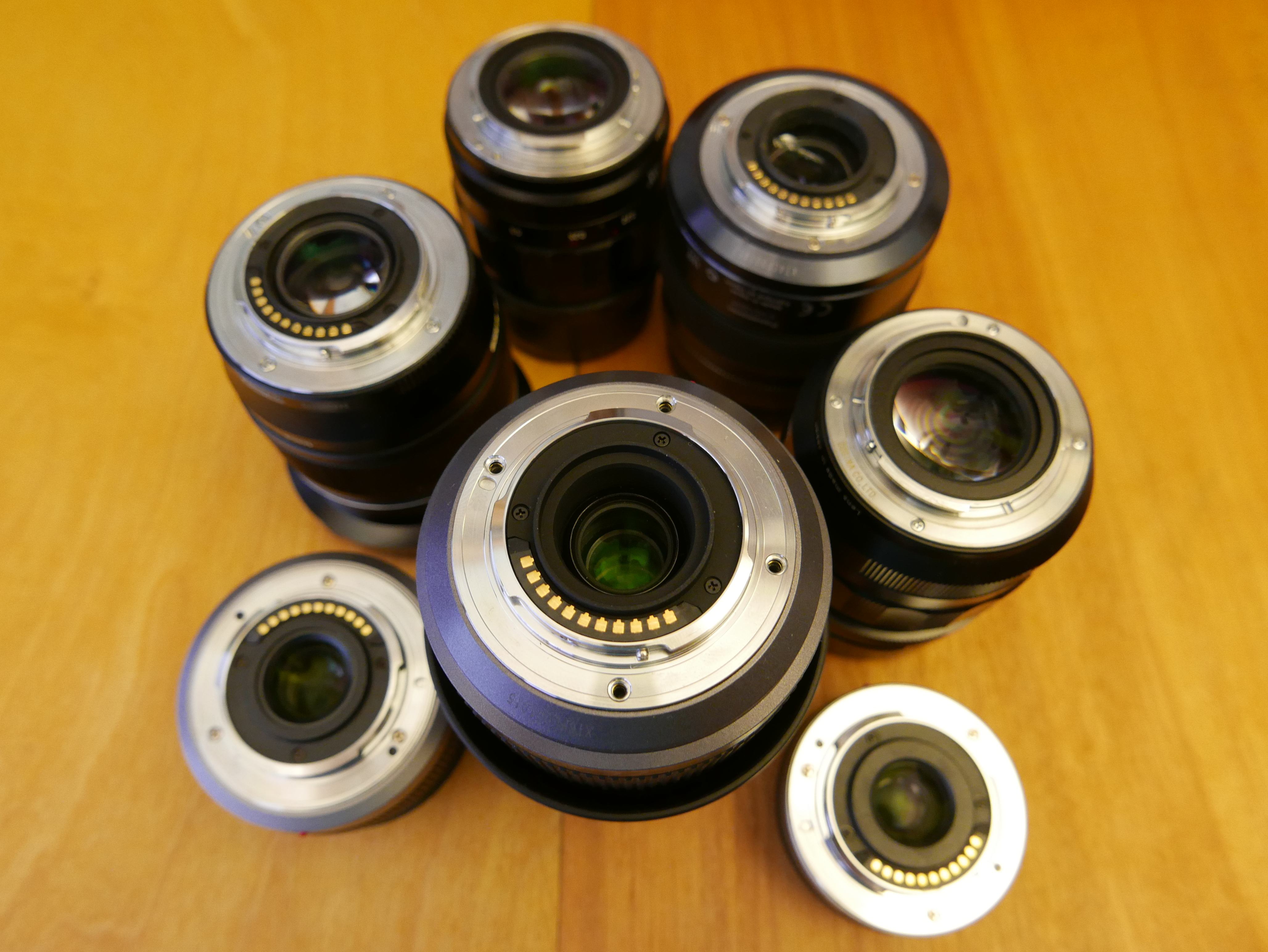
Some interesting notes about the Micro Four Thirds mount: I have noticed quite a variation in official Micro Four Thirds lens mounts. It seems that the thickness of the three flanged lobes that make up the mount are different per manufacturer. I am finding that Voigtlander/Cosina (49 thou) has a thicker flange than Panasonic (47 thou), Panasonic has a thicker flange than Olympus, and flanges on cheap third party mounts are about 41 thousandths thick and are not chamfered. Granted, heavier lenses may counteract the leverage placed on the mount by having a more rigid mount and thus thicker flanged lobes.
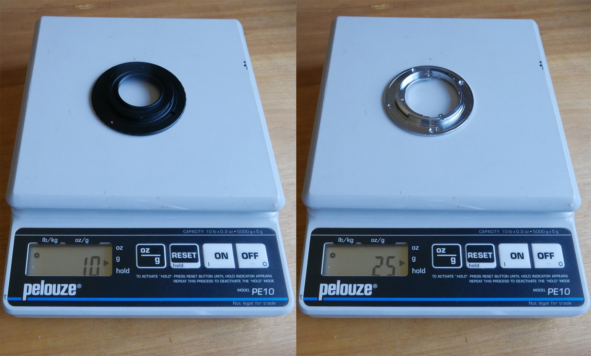
I did notice that the cheap c-mount adapter weighed about 10g, whereas the Panasonic mount weighed ~25g and consisted of far less material and volumetric space. In addition, it seemed that the Panasonic mount could hold an edge far better than the 3rd part c-mount adapter. I'll give you an example. When I finished the boring cut, my brother used his fingernail to debur the edge of the final cut. That is how soft the material is in the c-mount lens adapter! Doing that type of thing with normal grade steel or aluminum would sure spell out one cut up hand.
The bottom-most screw on the micro 4/3 lens mount, which is used to secure the 11 position electrical contact strip assembly, is co-linear to the red orientation dot on the exterior of the lens.
The overall outer diameter of u43 mount on weather-sealed lenses is smaller than traditional non-sealed lenses. This is to account for a small rubber o-ring which acts as the lens mount seal for the weather-sealed lens. Pretty nifty design change.
This is a shoutout to my youngest brother, Thomas Kouttron. Without his help, I would not have been able to get this project going as quickly as I liked. While I have experience with more modern lathe equipment, he showed me the ropes on the good old South Bend 9, and got me to a position where I feel comfortable enough to use it on a daily basis. Thomas is a machine shop TA at WPI, Worcester Polytechnic Institute. He is Haas CNC certified, has a beginning OSHA card, and just got his Solidworks certification. I am extremely proud of him and everything he does. Thanks again kiddo. You rock.
Want more? Here's a behind the scenes look at my workspace and some of the images that did not make the cut to be included in the write-up: