
Scooter Two: Super Scooter
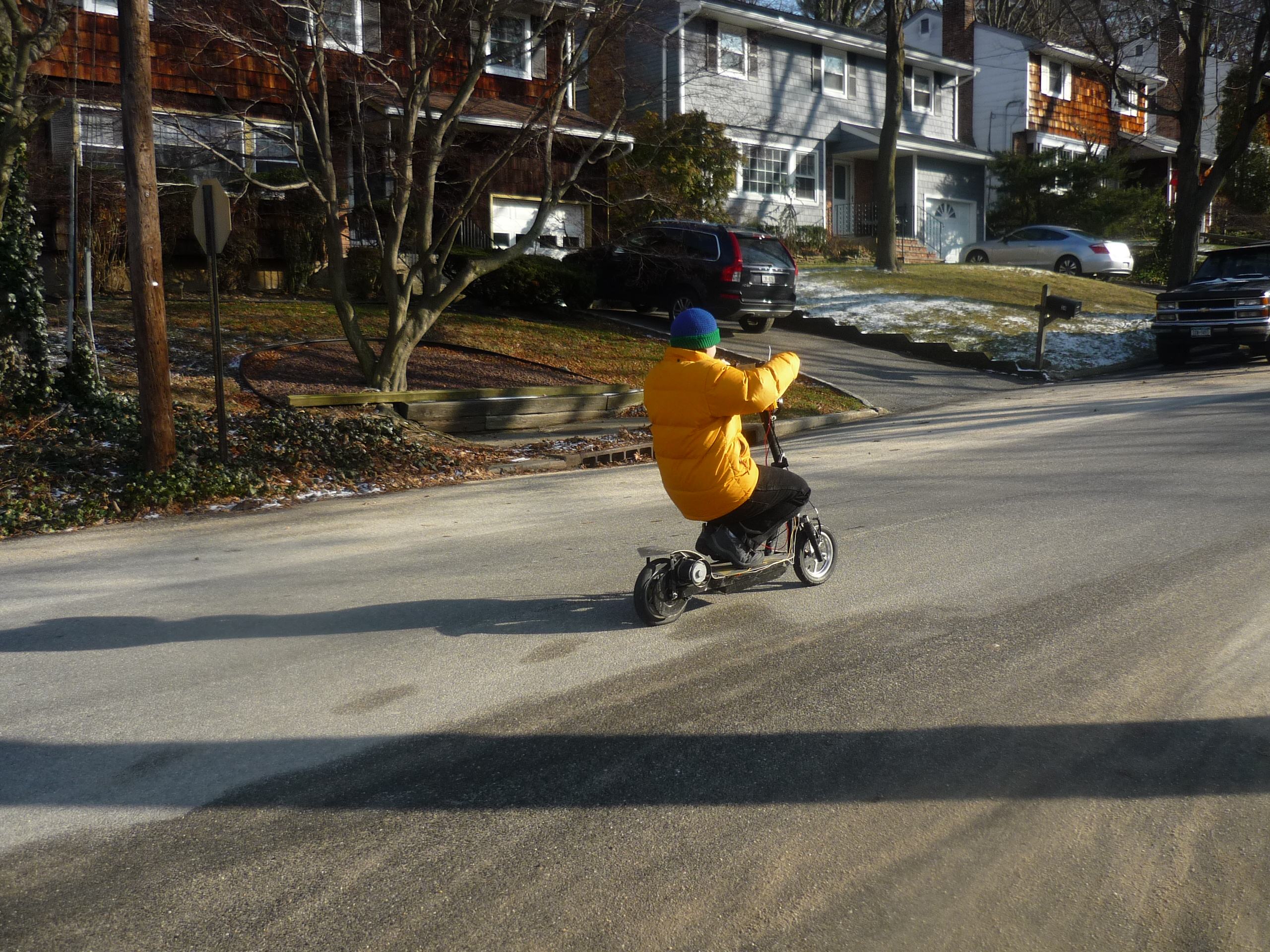
My scooter was pretty well factored into my daily schedule and saved me a bunch of time, so I wanted to make sure it didn't go down for any extended period of time. The best way to compensate for unexpected failures is to have a backup. Archivists rejoice! Welcome to Scooter 2.0, my super scooter. I took everything I learned from my first scooter build and applied it to another scooter with hopes of greater success and dependability. That was my original plan at least. The months following colored a totally different story. This scooter would become my showcase scooter, featuring everything and the kitchen sink.
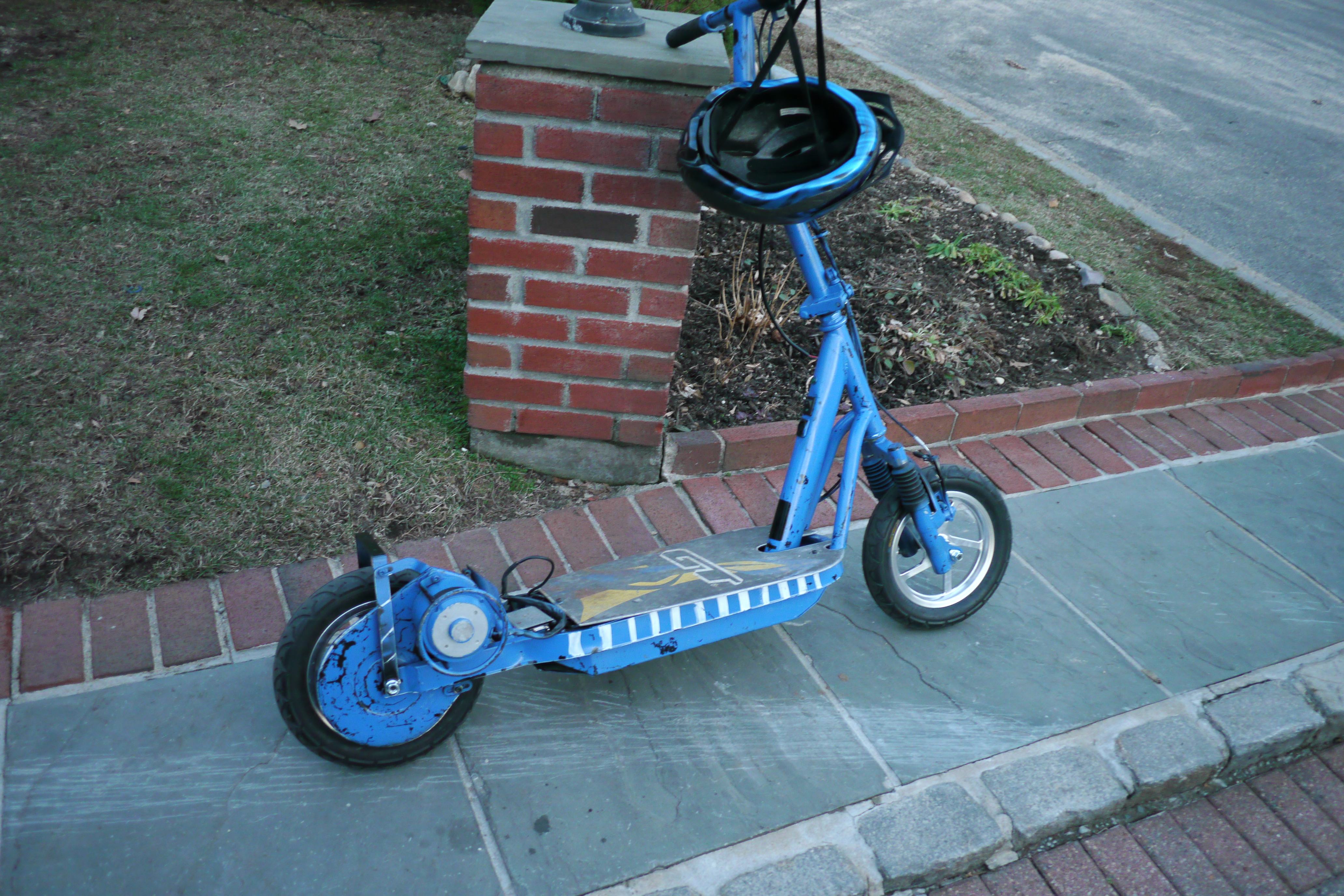
I picked up my second scooter during Christmas break 2013. Ugly huh. It's the perfect example of a "daddy I want a blue one" paint job. I started hacking my way through the forest in the same manner: I removed the seat, ditched the lead-acid batteries, upgraded to aluminum rims, swapped in a 12 x 3.0in rear wheel and repaired the breaks.

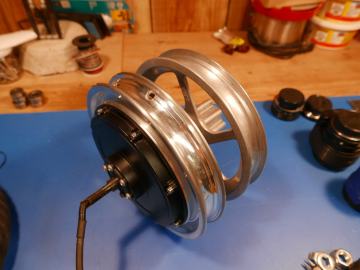
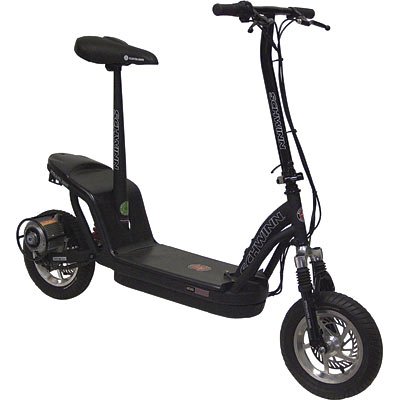
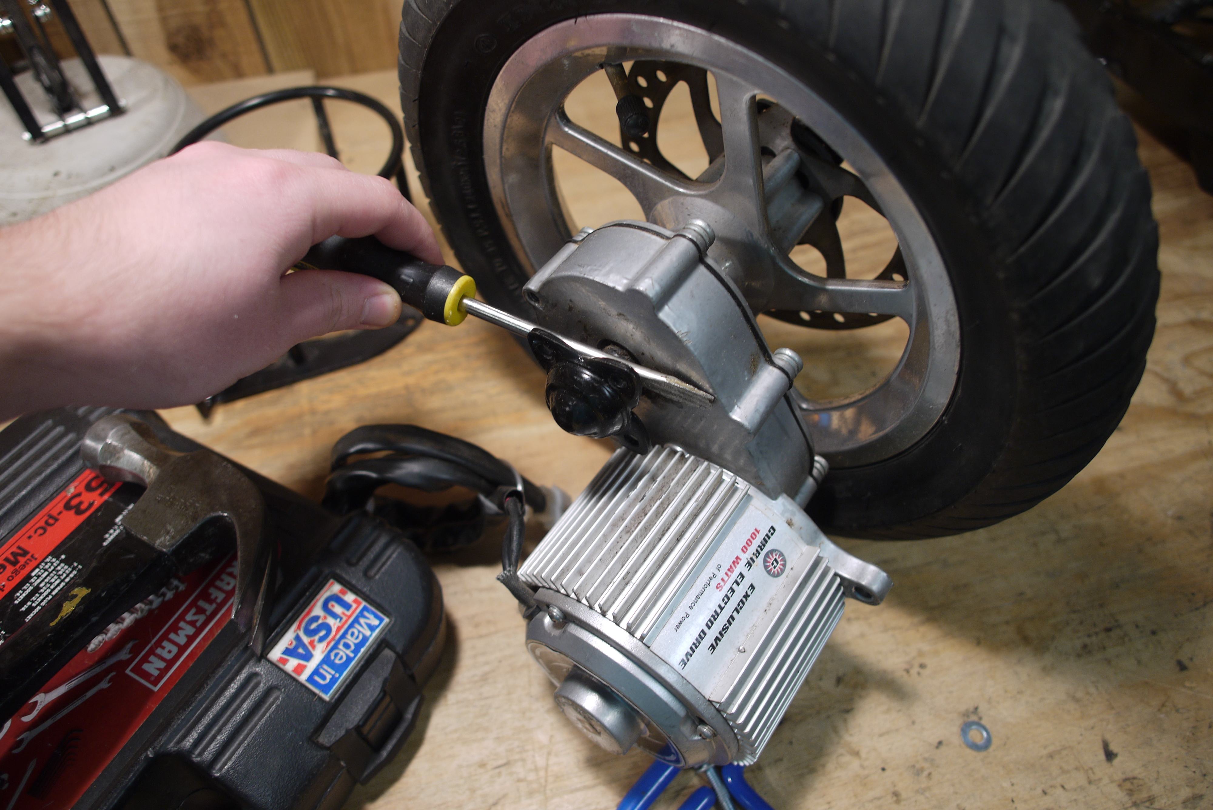
I got lucky with an ebay auction and ended up with a 1000w Currie motor and a spare front fork, both Schwinn Stealth 1000 parts. This is unfortunately how they came; with no packaging.
The Schwinn Stealth 1000 was the "greatest" scooter made by Currie and featured a 1000w motor, rear wheel bearings and a gearbox, a wider front fork for 12 x 3.0in tires and optional disk breaks.
As you could have guessed, the Stealth 1000 had it's own set of problems, and they were pretty substantial as well. Users of the Stealth 1000 complained that it could not freewheel and that it would completely shut off if they were going to fast. This guy's cool Human Electric Trike project shed some light on the issue. It looks like the Stealth 1000's controller featured over-current protection and would cut overall power to the scooter when a certain threshold was reached.
In addition, some users complained that the scooter would only last a few months before becoming completely unusable. Even with topped off batteries, the scooter would remain immobile or would skip when the throttle is pressed.

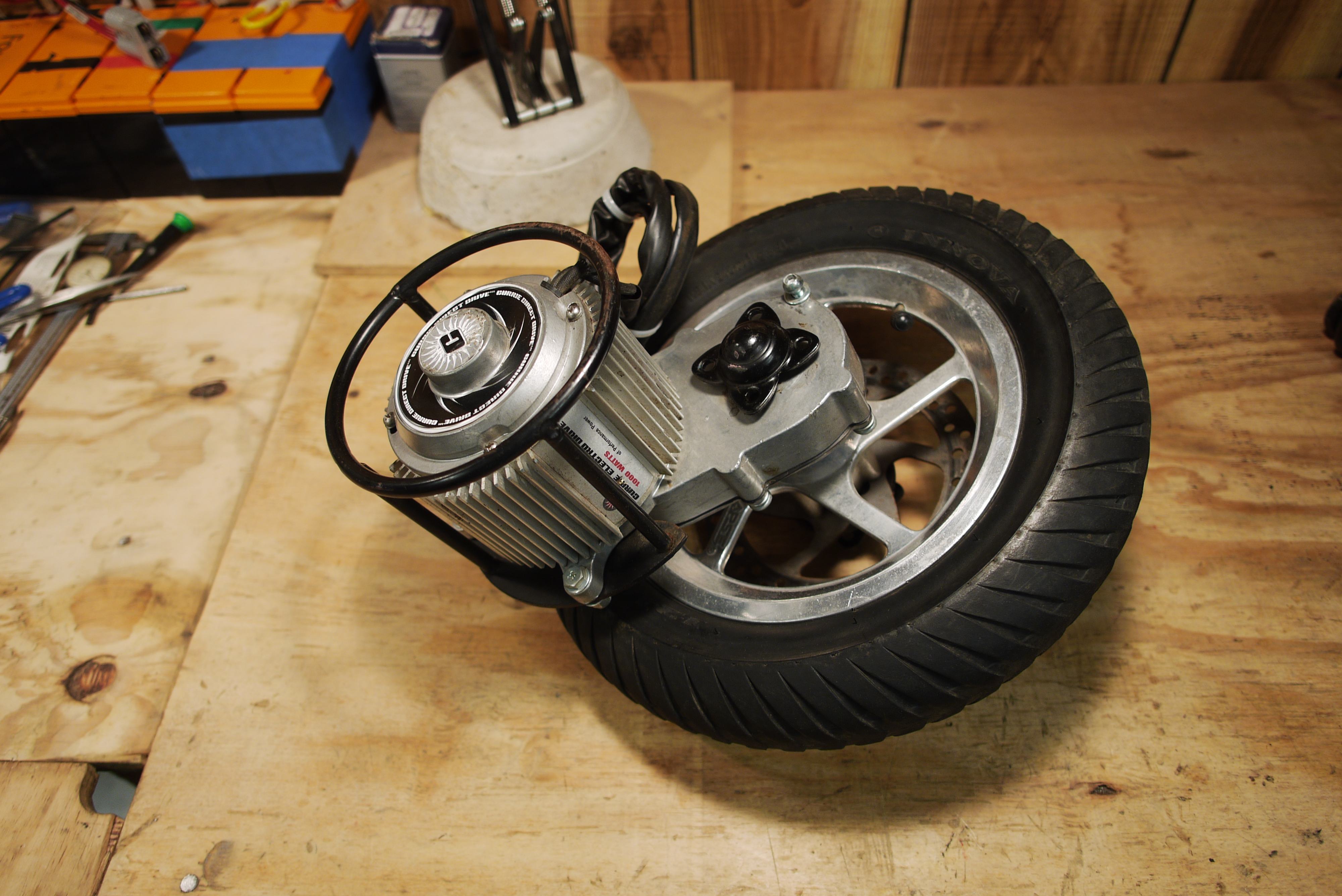
Here's a closeup on the Currie rear wheel motor and gearbox assembly. This model number of this entire assembly is XYD-18A. According to monsterscooterparts.com, there is another revision of this gearbox for the 2007 model year of Schwinn Stealth 1000 scooters.
Scoring this 1000w motor meant I could push the scooter harder than ever before and maybe finally approach that 28mph legal limit for 50cc class scooters. Ideally, I wanted my scooter to fear no hills, and this motor would be a major stepping stone toward getting me to that point.
Since the 1000w motor was pretty important to making my super scooter super, I'm going to take some time and analyze the motor and gearbox assembly.

Removing the 1000w motor from the gearbox was relatively straight forward. Start by removing unnecessary external items, like the motor protective cage and mounts. This is just a few simple nuts and bolts.
To get to the axle, you first need to remove the wheel bearing cup on the end of the shaft. I found that the least destructive method of removing the bearing cups was to use one or two flathead screw drivers and gently prying them away from the nearest work surface. This would force the bearing cup off the bearing, and the bearing would come free with little persuasion.
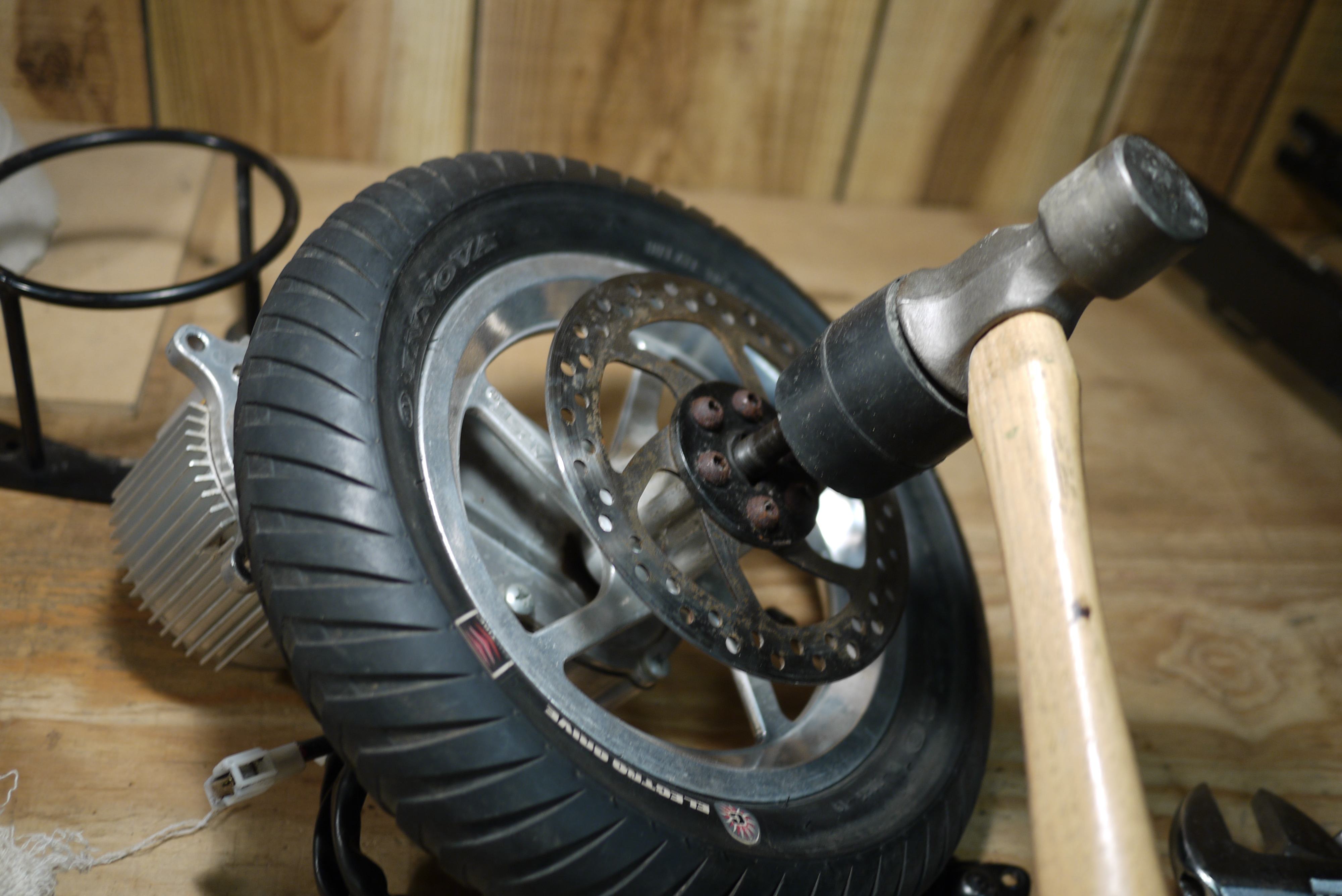
With the bearing removed, the only roadblock left was a metric nut. With the nut removed, I used a rubber mallet to force the keyed axle out of the keyed rim. This far in, it looks like Currie learned a thing or two from their previous scooter designs. The gearbox and shaft assembly were free from the rim and disc break assembly.
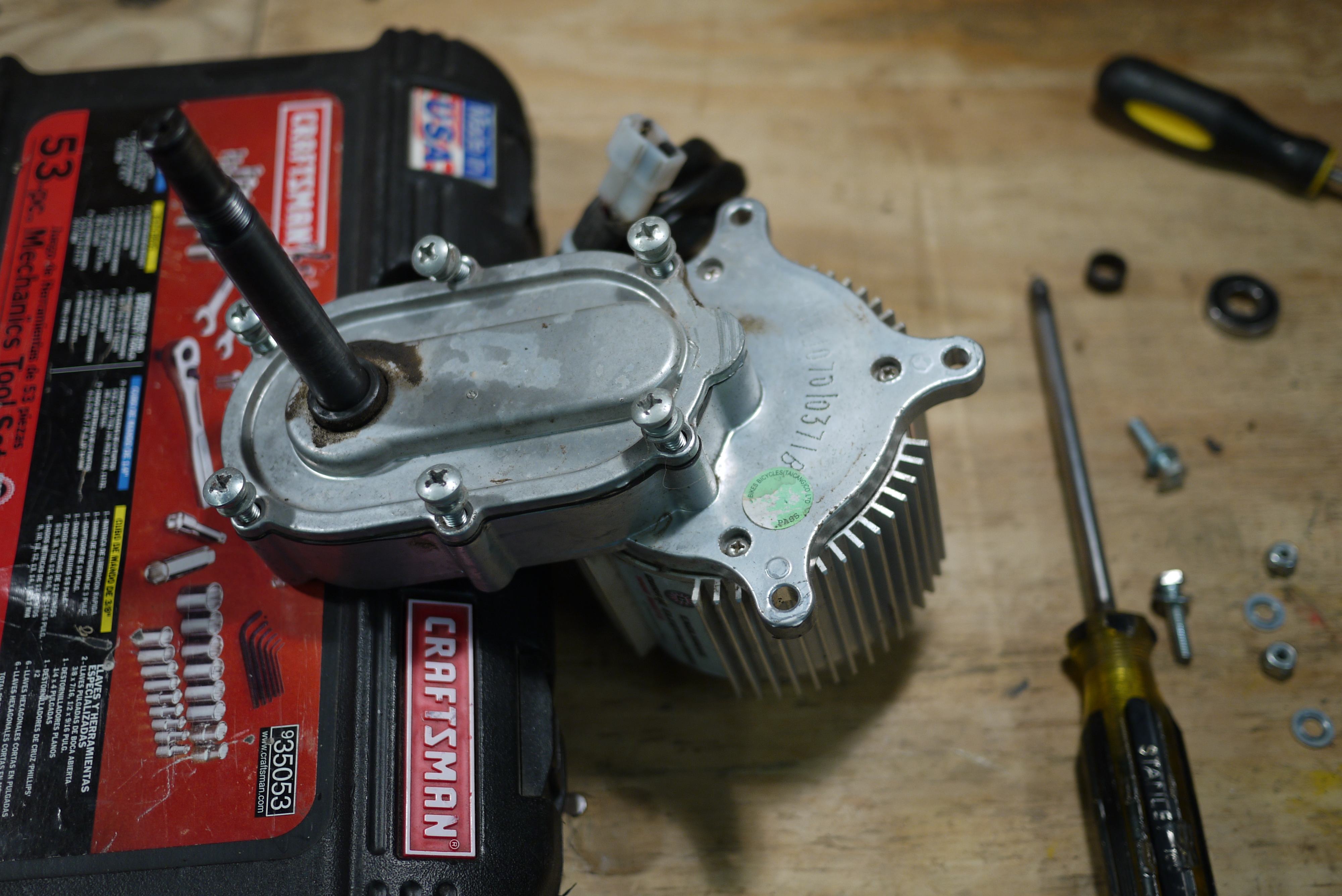
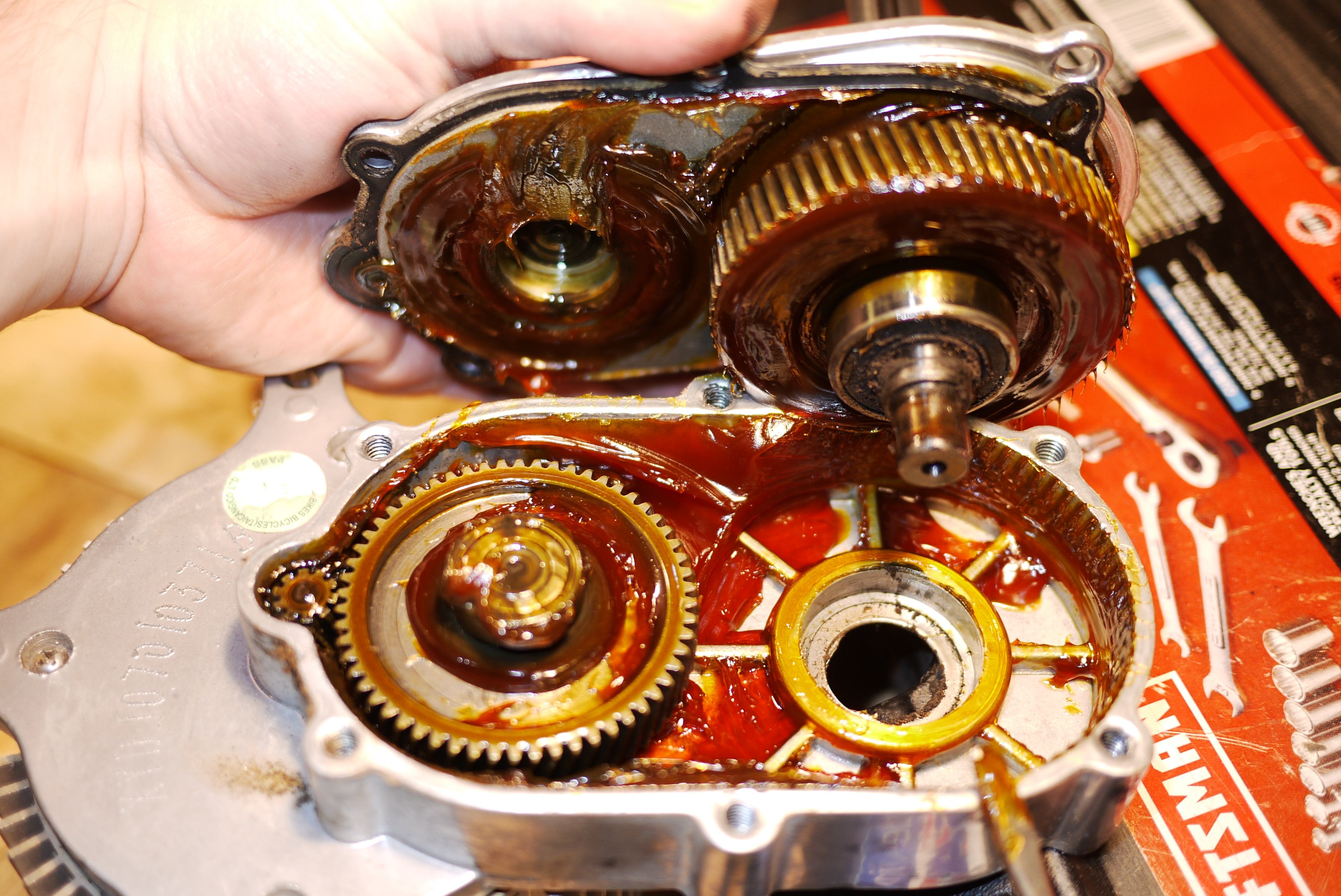
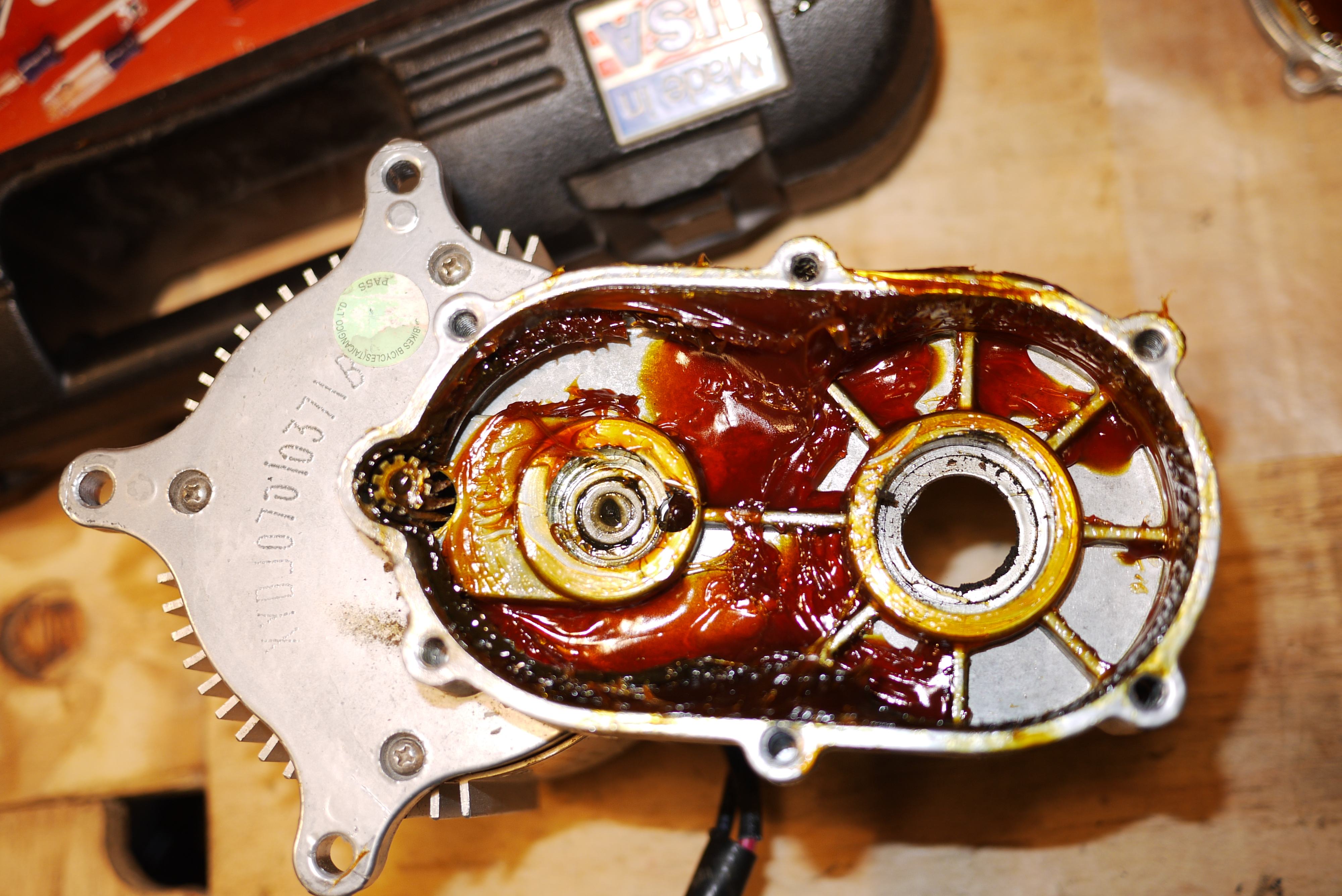
With the removal of the 6 main Phillips screws and a tap of the rubber mallet you were inside the business end of the gearbox. When I saw the gasket I took a good double-take. Someone finally put some thought into this.
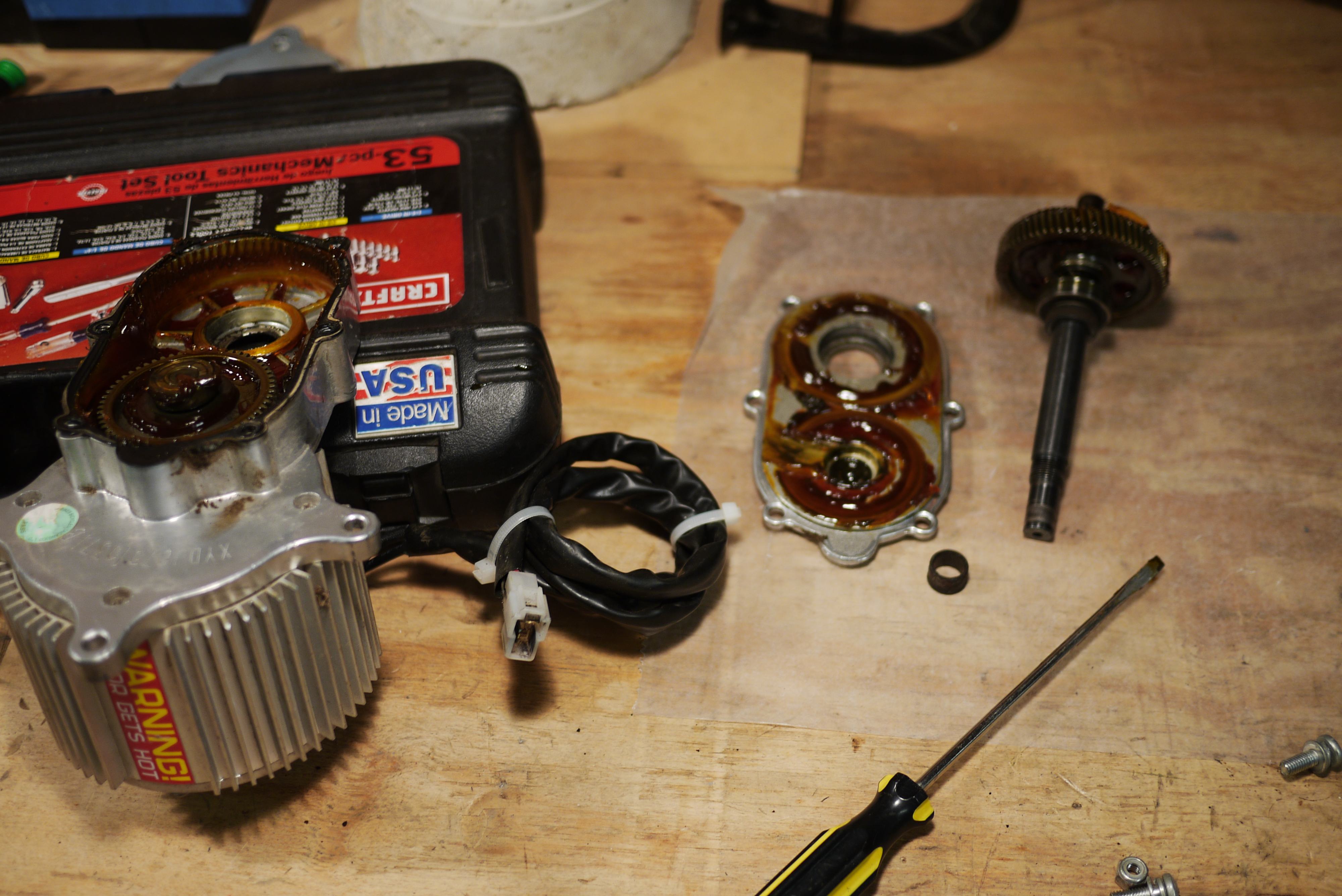
Honestly, the hardest part of the entire procedure was keeping the transmission grease off of the work surface, tools and your hands. I used wax paper to protect my table from staining.
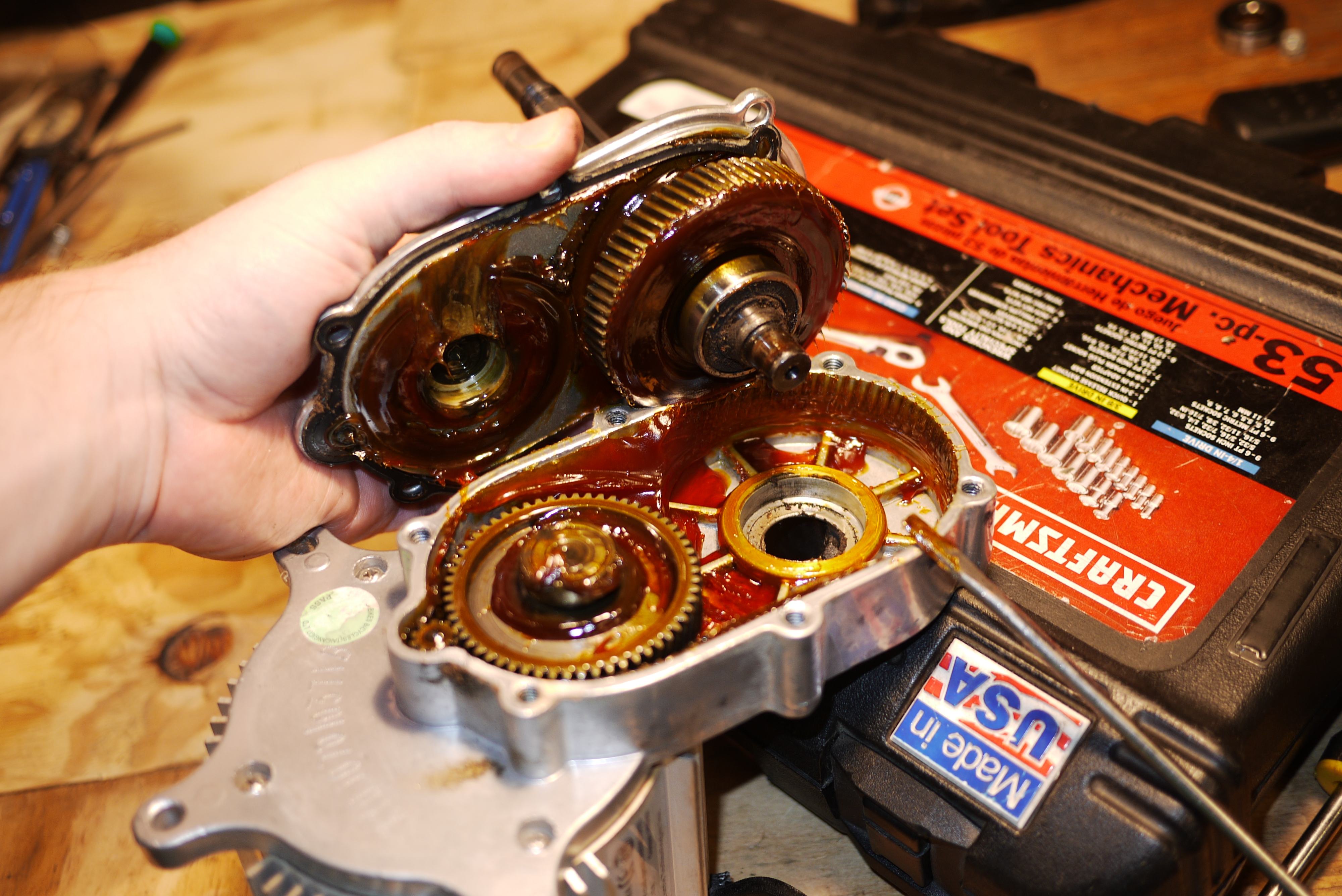
It turns out, the gearbox Currie implemented was an afterthought as well. The exterior design looks fairly decent. It is a cast aluminum or magnesium housing with properly broached gears. None appear to be powder sintered gears either. There is even a decent transmission-like grease used that is fairly viscus.
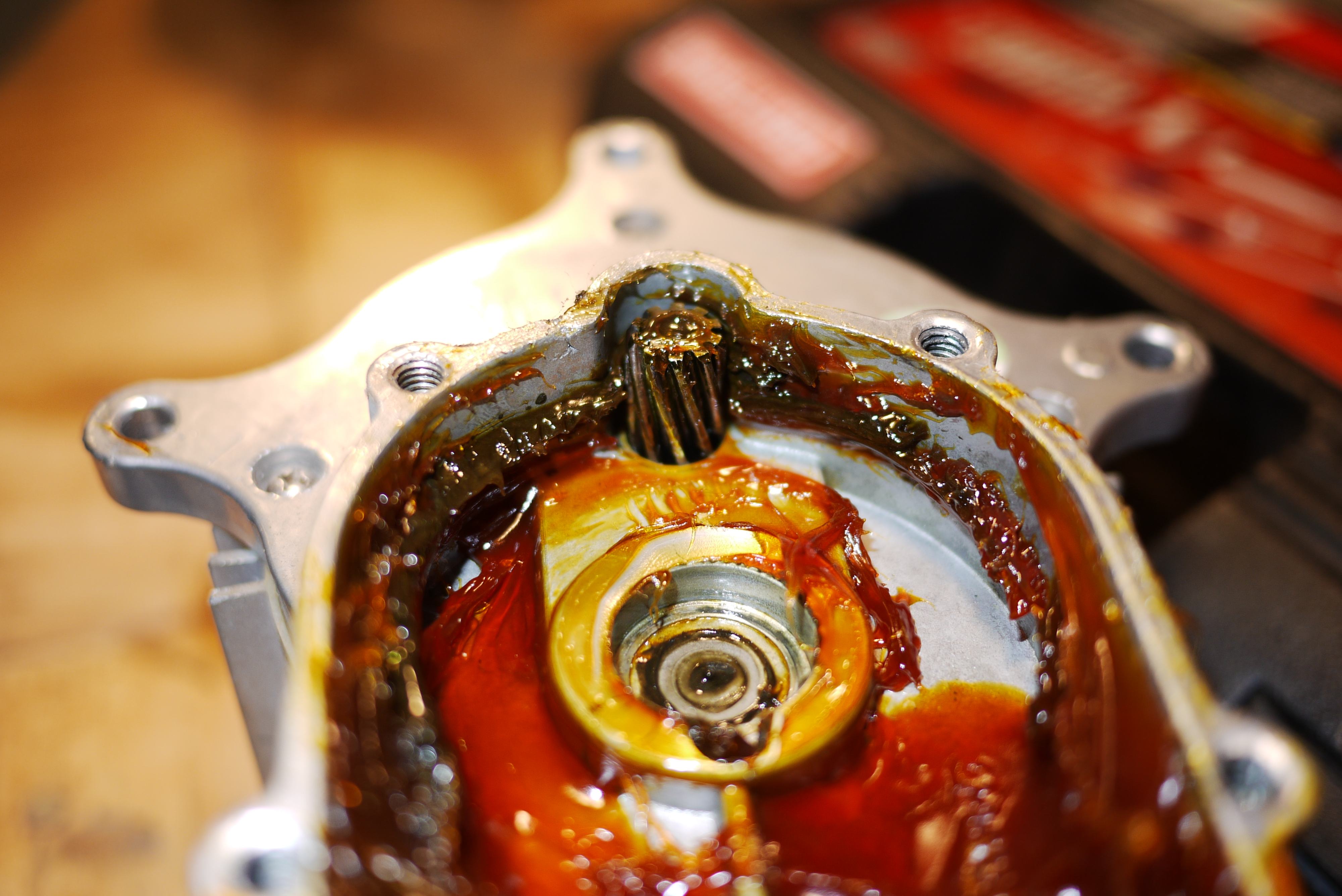
However, the Achilles' heel was the poor design choice of machining the end of the motor shaft into a helical gear. Even if the motor shaft was hardened and properly ground, it features the smallest load transfer surface and has the greatest potential to wear first.
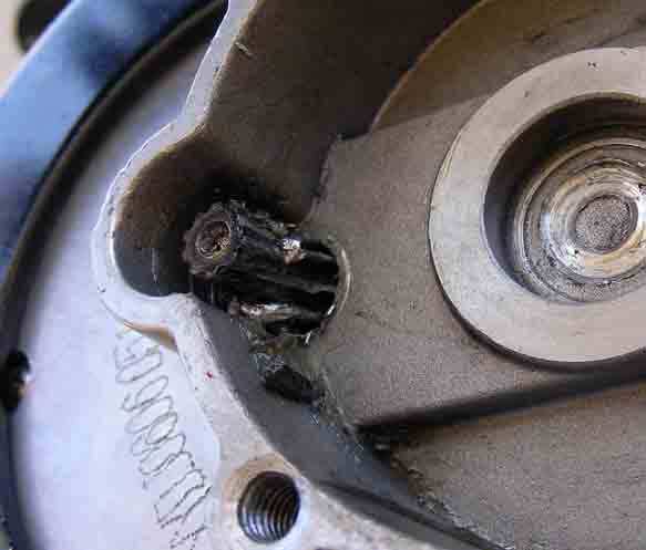
Sure, the gearbox would work great for a few dozen hours of climbing hills before the helical teeth would round out and wear down the motor shaft to a nub - but then your scooter was completely toast. This is a shot of a broken 1000w Currie gearbox. Almost 1/3 of the helical shaft gear is not worn, indicating that the contact between gears was not ideal and the gears were not properly co-linear. This could have been an error in assembly, poor design or a little of both.
This particular design design is disheartening, as there is no quick fix for the awesome DIY parent ready to fix their child's failed birthday present. You couldn't just open up the gearbox and replace a gear and button it back up and be done. No. You would literally need a new motor, and then again you would only get a few dozen more hours on that too. You can see why I was able to get this 1000w motor so cheap.
To my surprise, the helical gear on my 1000w motor was not that chewed up, so the stealth 1000 it came out of must have not been used that much.
There was one issue though, the top gearbox housing was the top cover of the motor, making the motor removal less than idea. Sure, the most important parts of the motor, the rotor and stator, were easily separable, but the top cover would be unrecoverable.
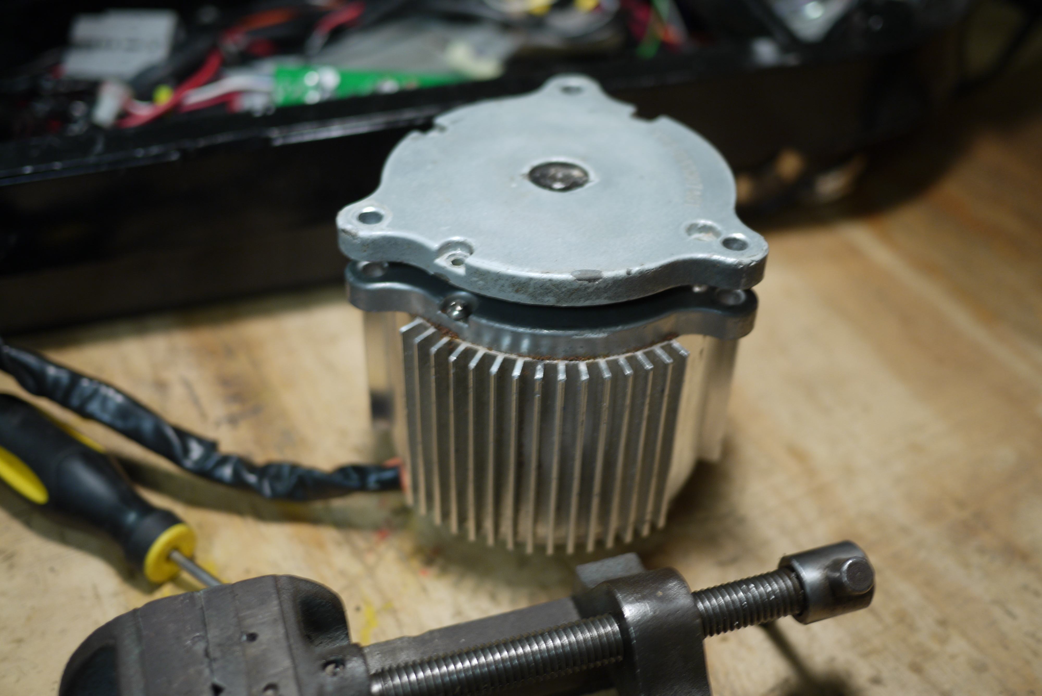
The good news is that Currie recycled motor designs like nobody's business. The motor cap from their 350w, 640w and 840w motors interchanged with the 1000w motor. This not only helped them save overall manufacturing costs, but solved a lot of headaches for me later down the road.
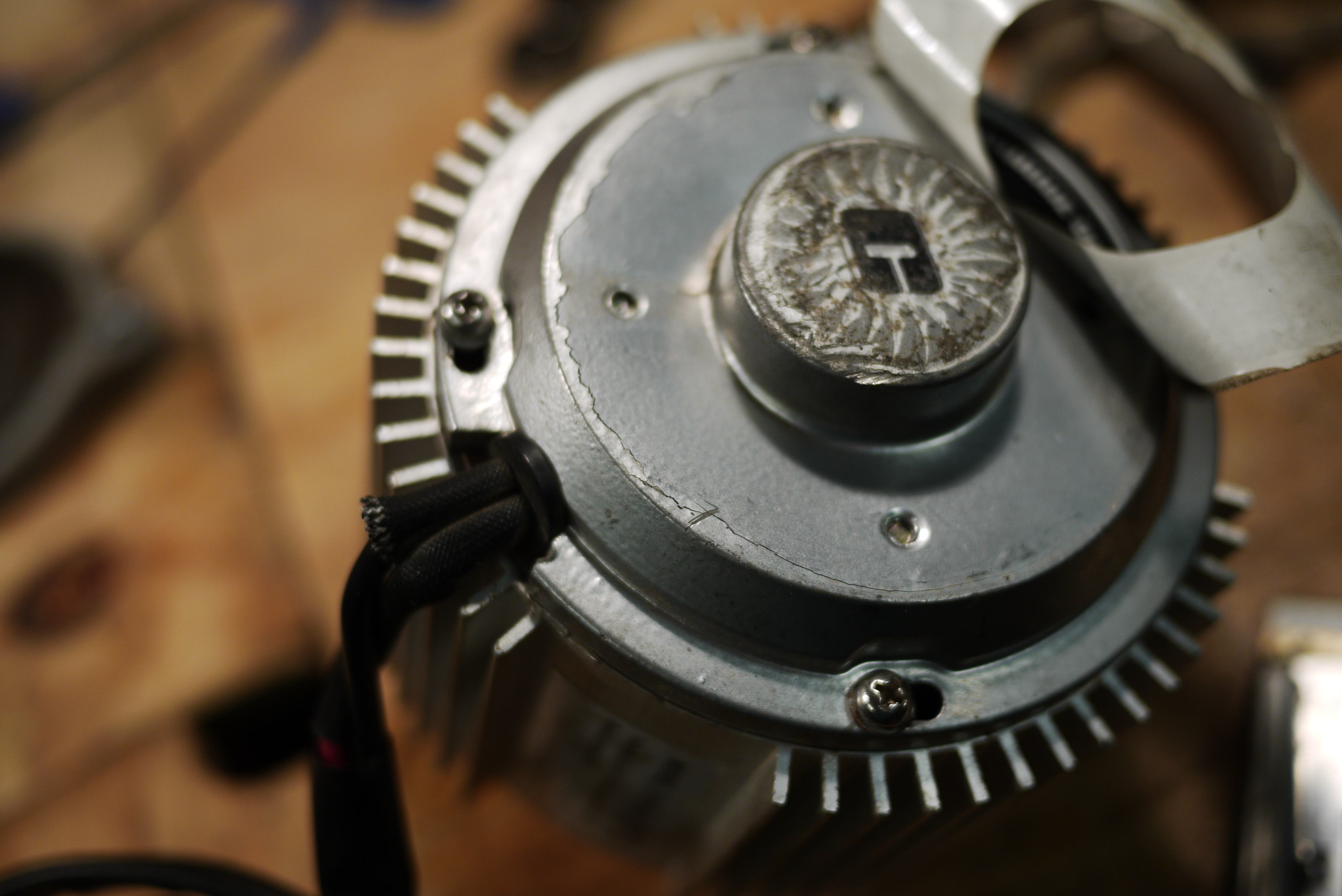
When I finally freed the motor from the gearbox assembly, I admired the little chunky finned motor and peeled off the rear motor label in pride. Then came the dreaded bit: the motor end cap was damaged. I hadn't noticed the damage until I removed the sticker because the sticker camouflaged the crack in the casting pretty well.

The damage looked a lot worse from the inside. The crack in the motor cap casting offset the motor rotation axis. Luckily the main bearings took most of the damage and the axle appeared undamaged.

Luckily, all was not lost and I was able to swap on a motor end cap from another weaker motor.
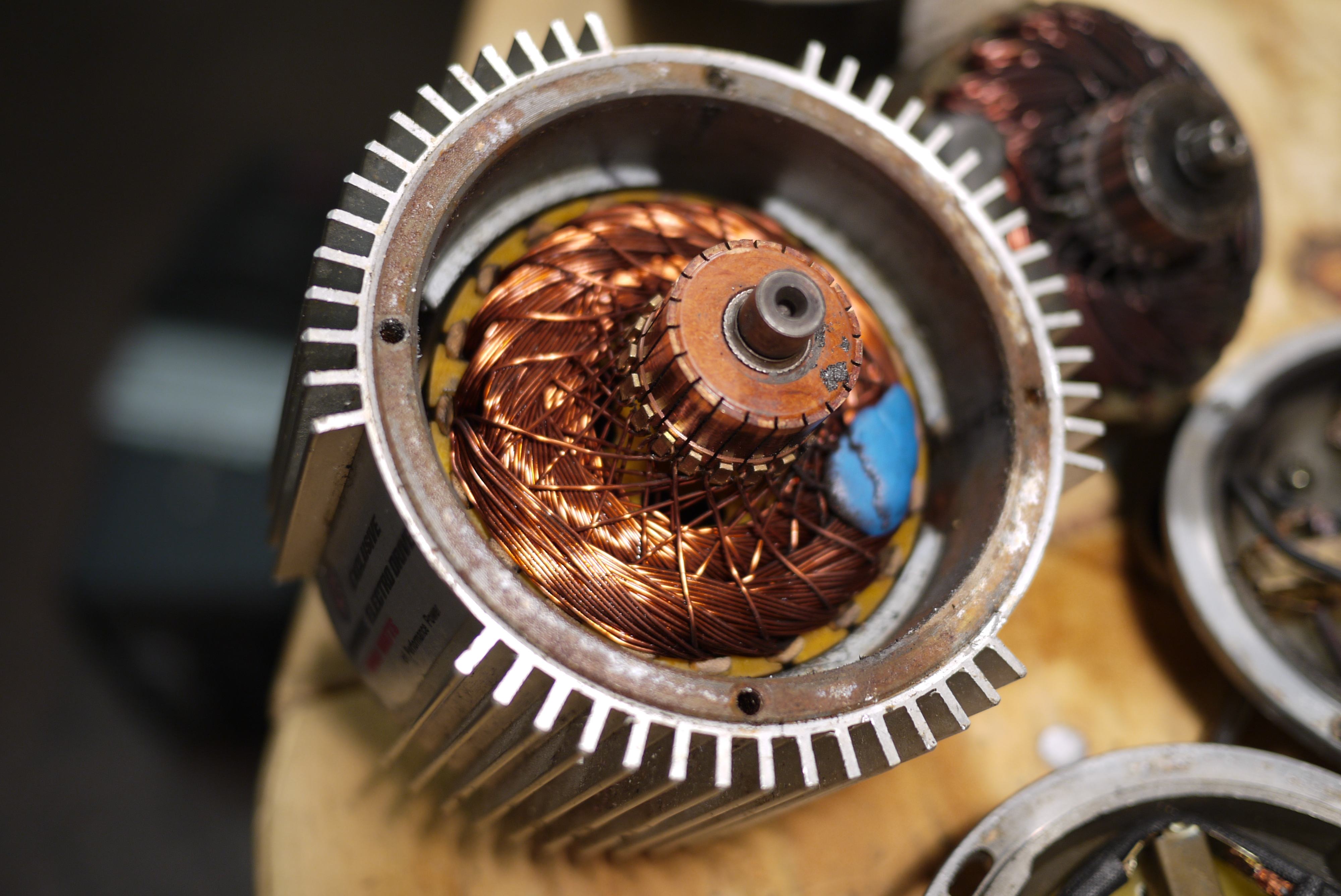
While I was inside the motor I decided to take a closer look at the 1000w motor and compare it to the other Currie motors I had. On first glance the motor looked okay. Not the best construction, but at least the windings looked to be wound fairly tight.
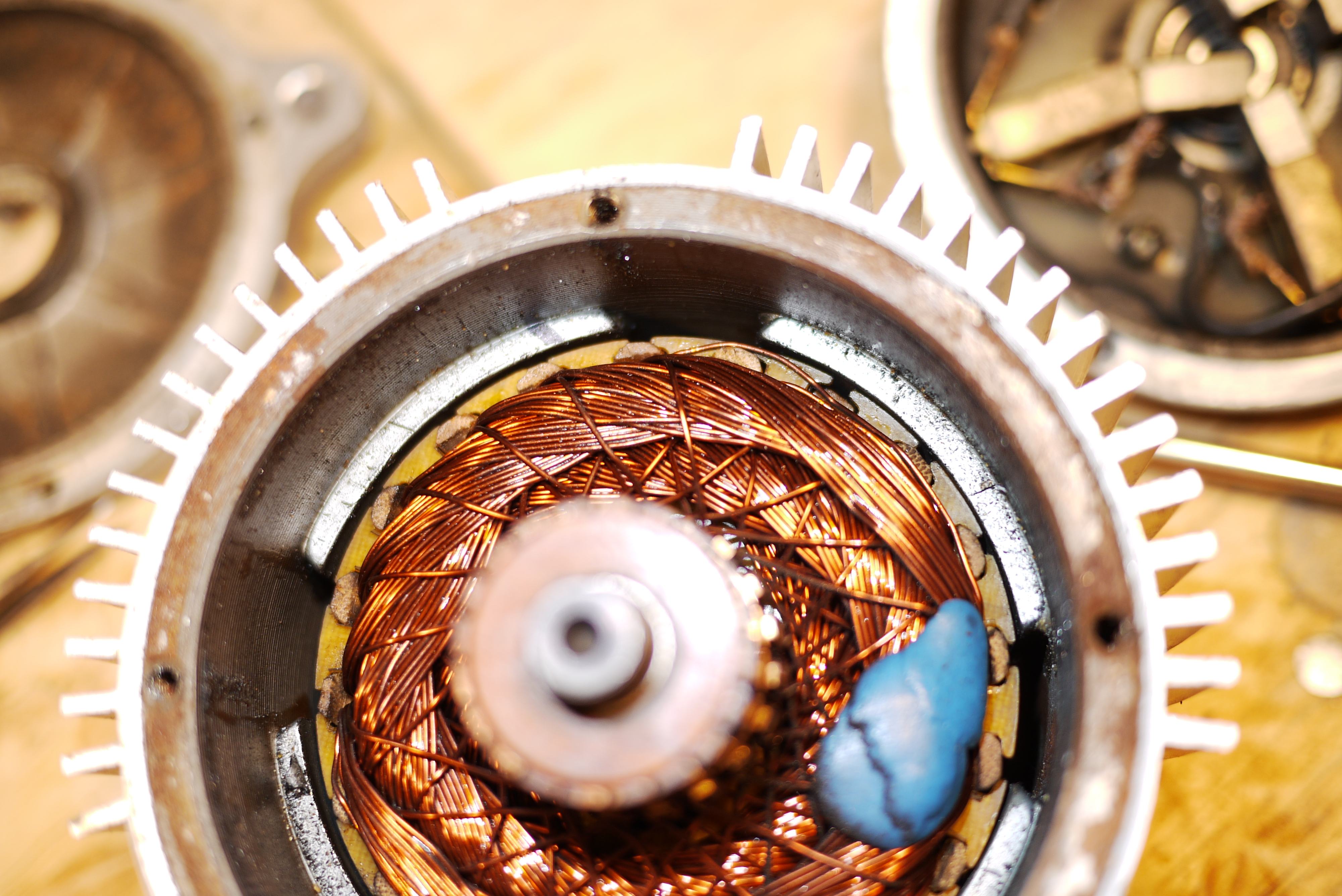
I guess I spoke too soon. That wire clearly could have caused problems sooner than later. I obviously don't want a dead short as a motor, so that's going to have to be fixed.
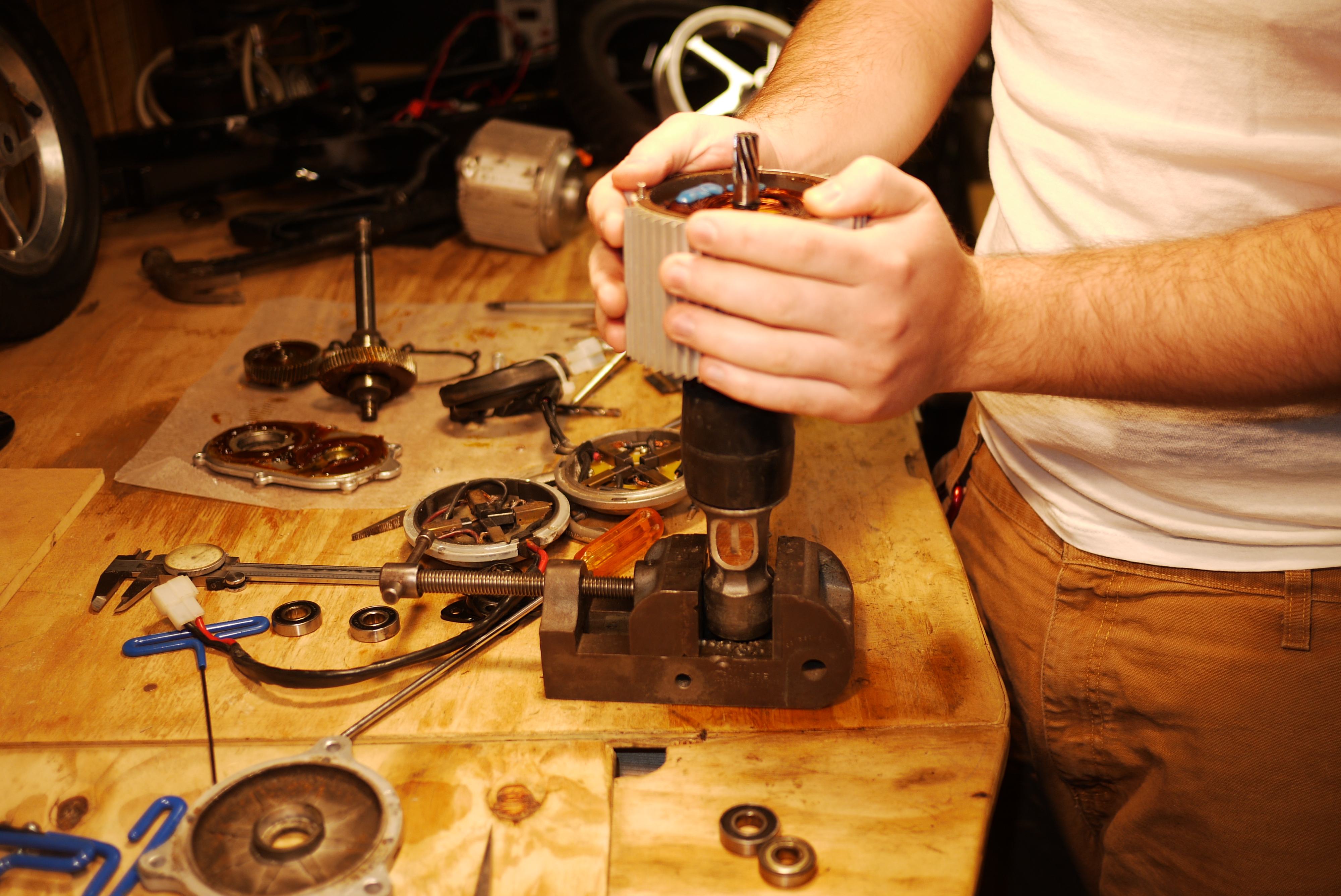
To even get to that point required the rotor to be separated from the stator. The neodymium magnets sure made it a challenge to remove the rotor and I settled on using a drill press vise, a hammer and my weight to push down on the stator. I had my brother on standby to catch the rotor when it was outside the magnetic field of the neodymium magnets.
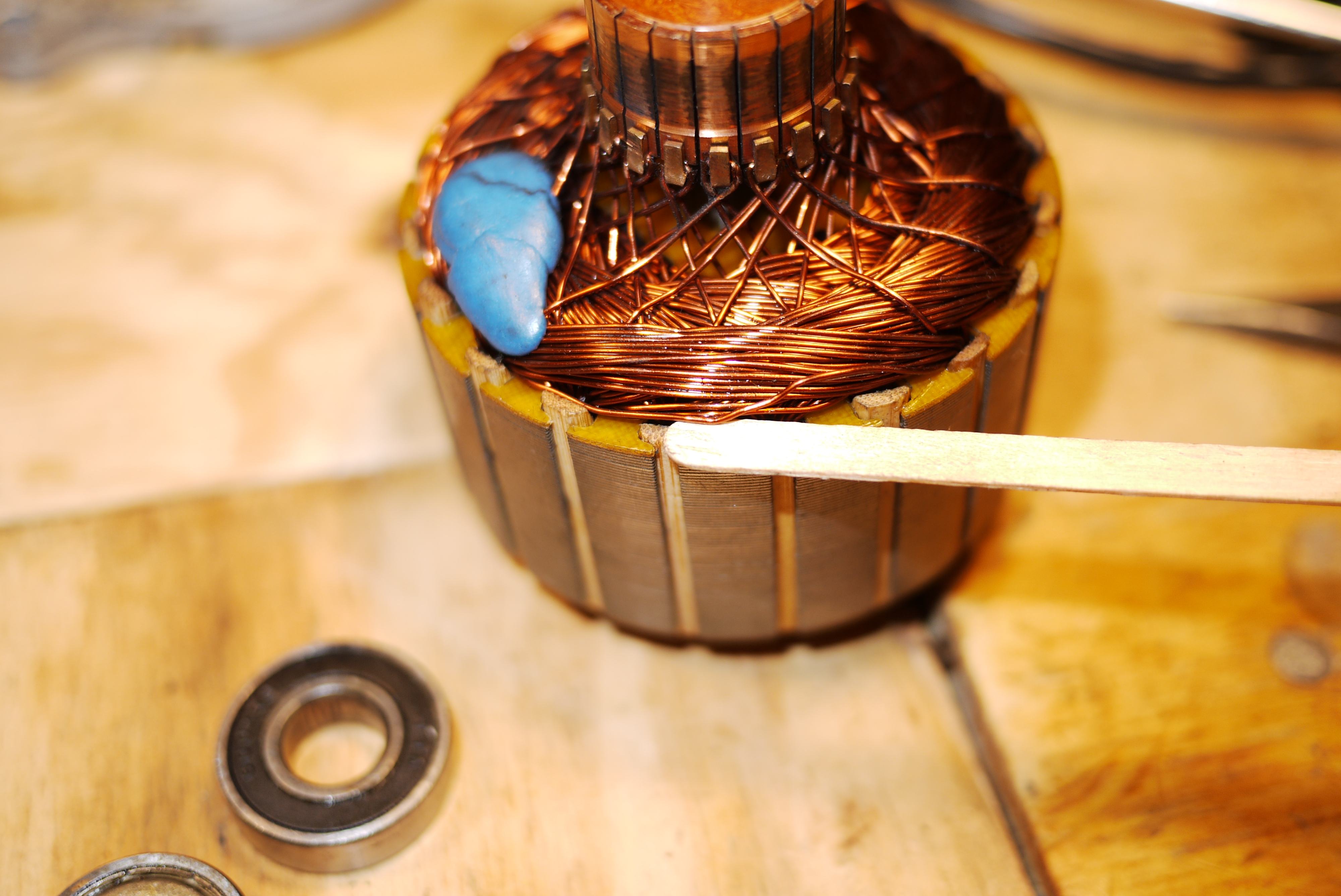
I maneuvered the winding further toward the center of the rotor axis using a thin popsicle stick. It is important to remember that these wires are enamel coated to prevent the windings from shorting together. Magnet wire has a very thin layer of insulation and is quite fragile, so it is imperative that you use a blunt, soft object to move them.
Keep in mind I was only able to move this winding so easily because the Currie motor does not feature epoxy covered ends. Well built motors often use epoxy to fix armature windings in place so they don't come loose from the soldered connections to the commutator segments. The epoxy also doubles as a way to ensure the windings stay taught and don't get caught between the rotor slots and the walls of the stator.

I bet you are curious about that blue glob on the motor windings. Well It's not epoxy, that's for sure. It looks to be some type of wax used to balance the motor. Traditionally, motor manufacturers balance the rotor after the epoxy has cured and cut grooves into the top faces of the laminations to compensate for any off axis weight. In this case Currie (or whatever company who made the motor)opted to use wax, presumably for cost savings.

One really unexpected cost savings measure is almost unnoticeable. I'll give you a hint: look at the insulation used in between the rotor laminations and the winding groups. Yup. That's right. It's bamboo. It looks like the motor manufacturer used non-uniform cut-to-length segments of bamboo chopsticks to serve at the insulation instead of plastic inserts, epoxy or even mica paper. When I first noticed this I just couldn't contain myself. Unbelievable.
I buttoned up the motor as much as I could and looked up some replacement bearings. Meanwhile, I reverted back to the stock motor setup and shifted focus to removing that spray-paint-overhaul blue from the scooter. I mean, I wanted to be able to differentiate between my two scooters, but I was a bit over the whole white racing strip days.
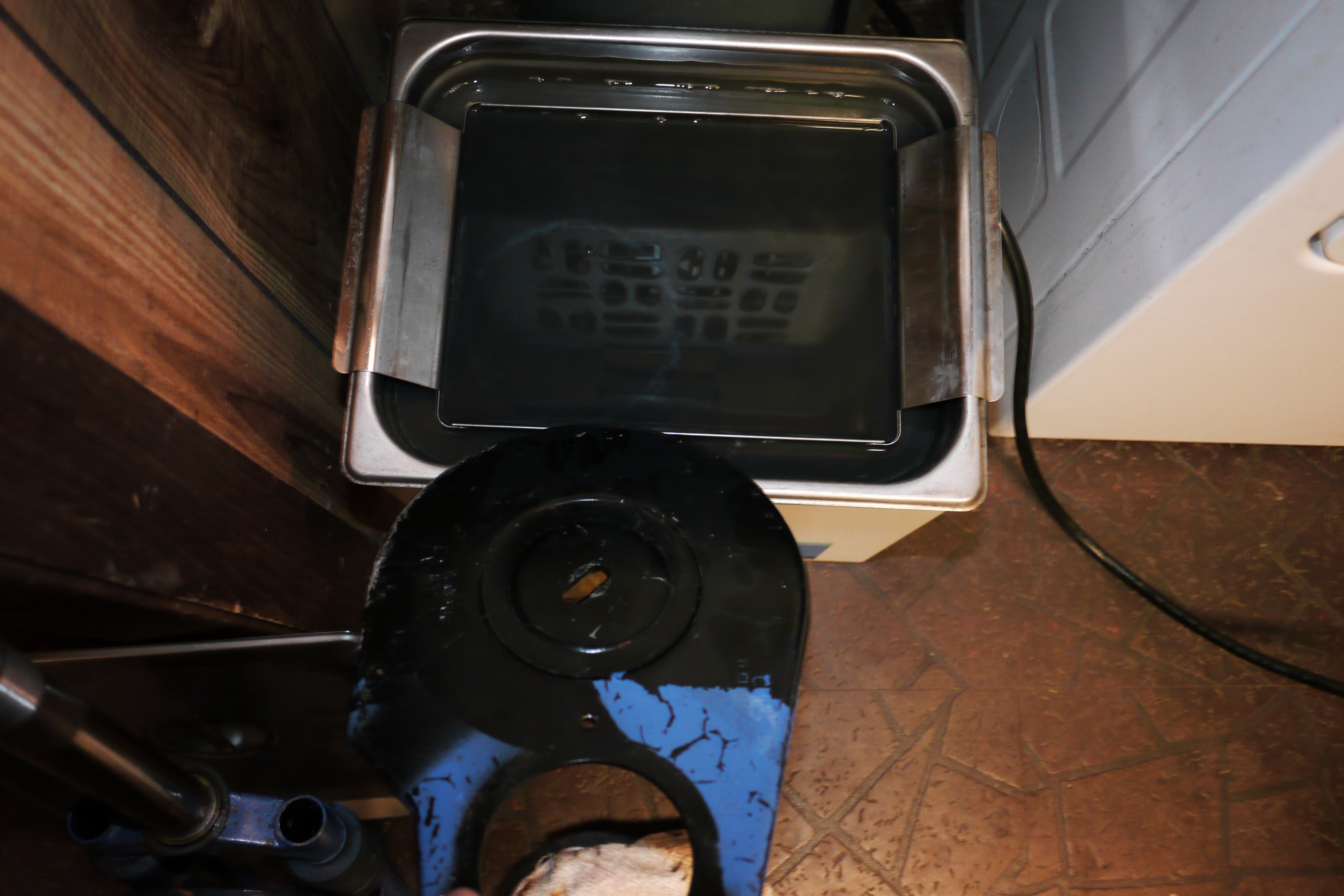
I began stripping the scooter of parts, and putting the small ones in my newly acquired ultrasonic machine. The combination of the penetrating sound waves and a heated tub made quick work of removing the annoyingly blue paint.
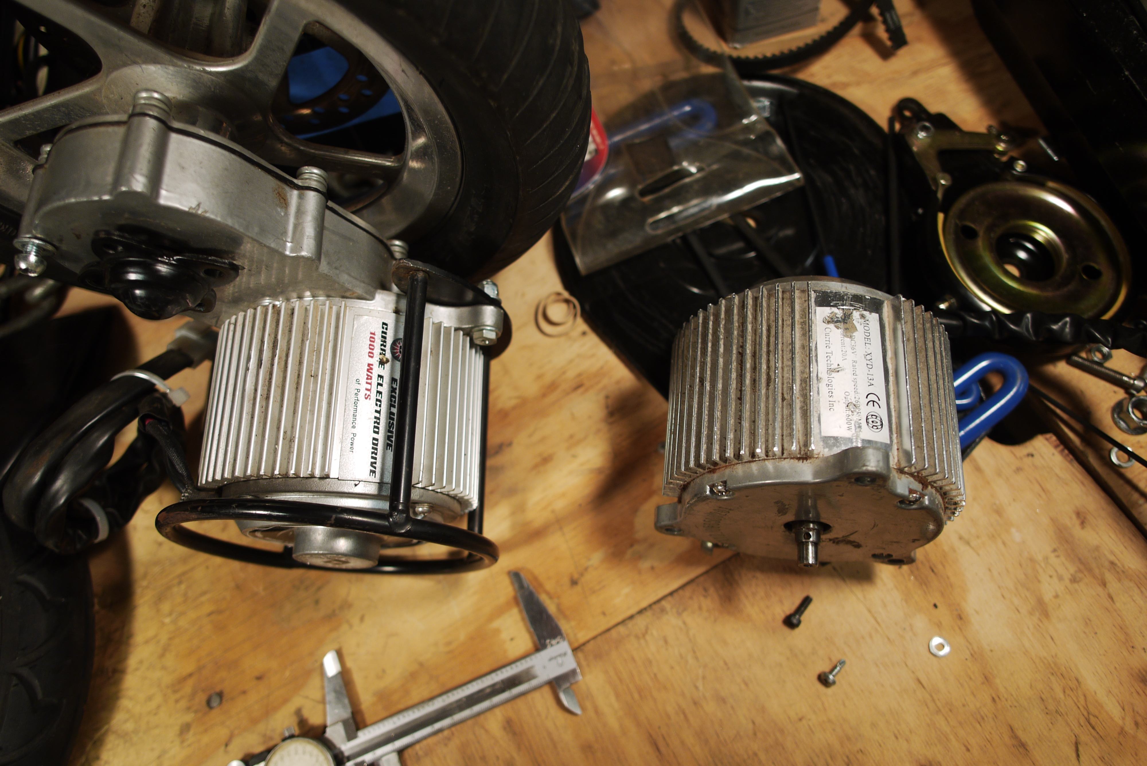
A few weeks later, my brother stopped by with a "600w" XYD-13A motor, which looked to be the same one used in the "1000w" XYD-18A unit. I went ahead and used the XYD-13A motor for the time being.
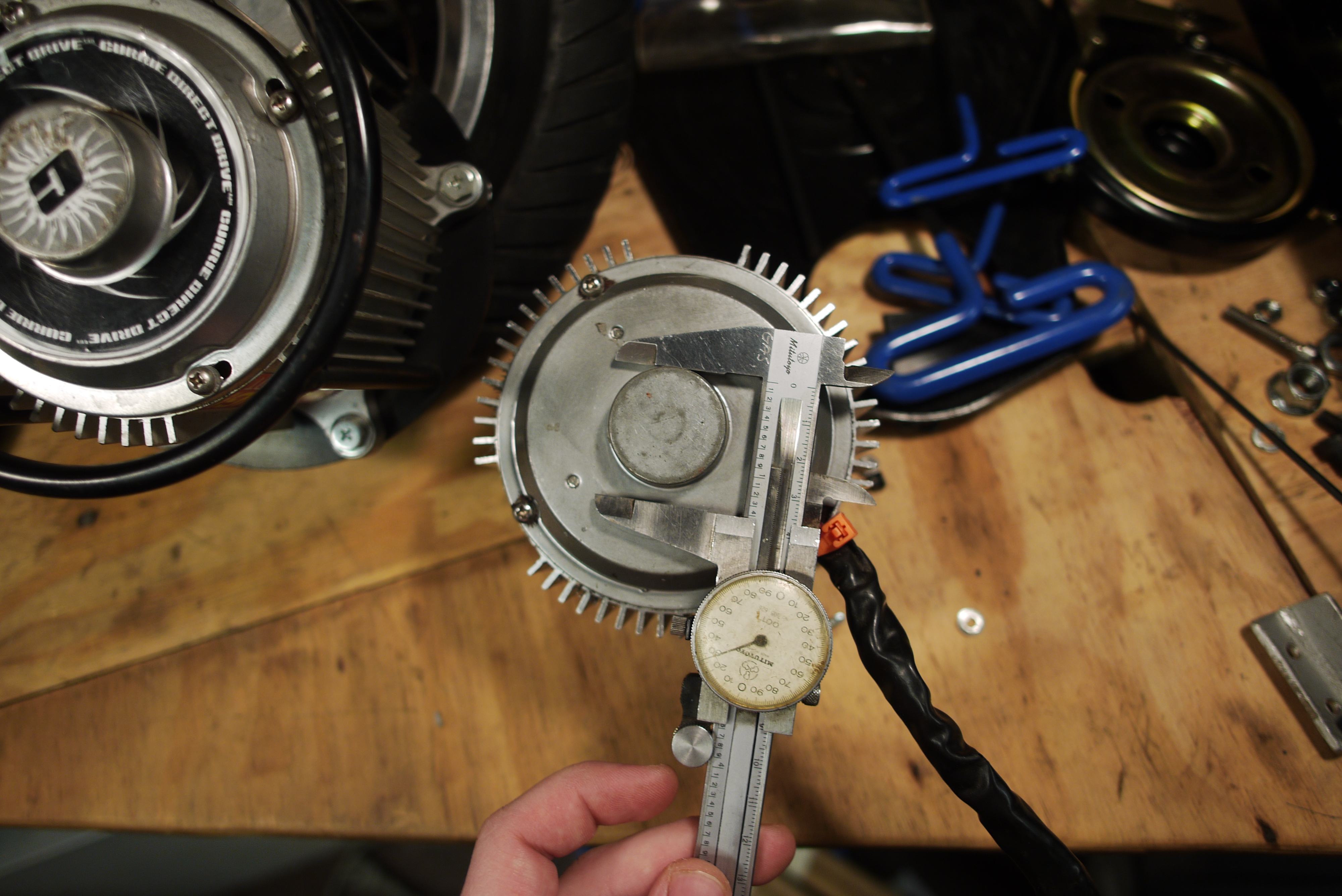
The only notable difference was the size of the bearings used in the end caps of the motor. The caliper measurement represents the exterior diameter of the XYD-18A motor bearing housing.
As much as I hated the stock motor mount mechanism, the XYD-13A had the ability to just swap into place of the old ferrite magnet motor. The sprocket would transfer over as well. This meant that if I salvaged the old mount, I could save a lot of time by not designing something new.
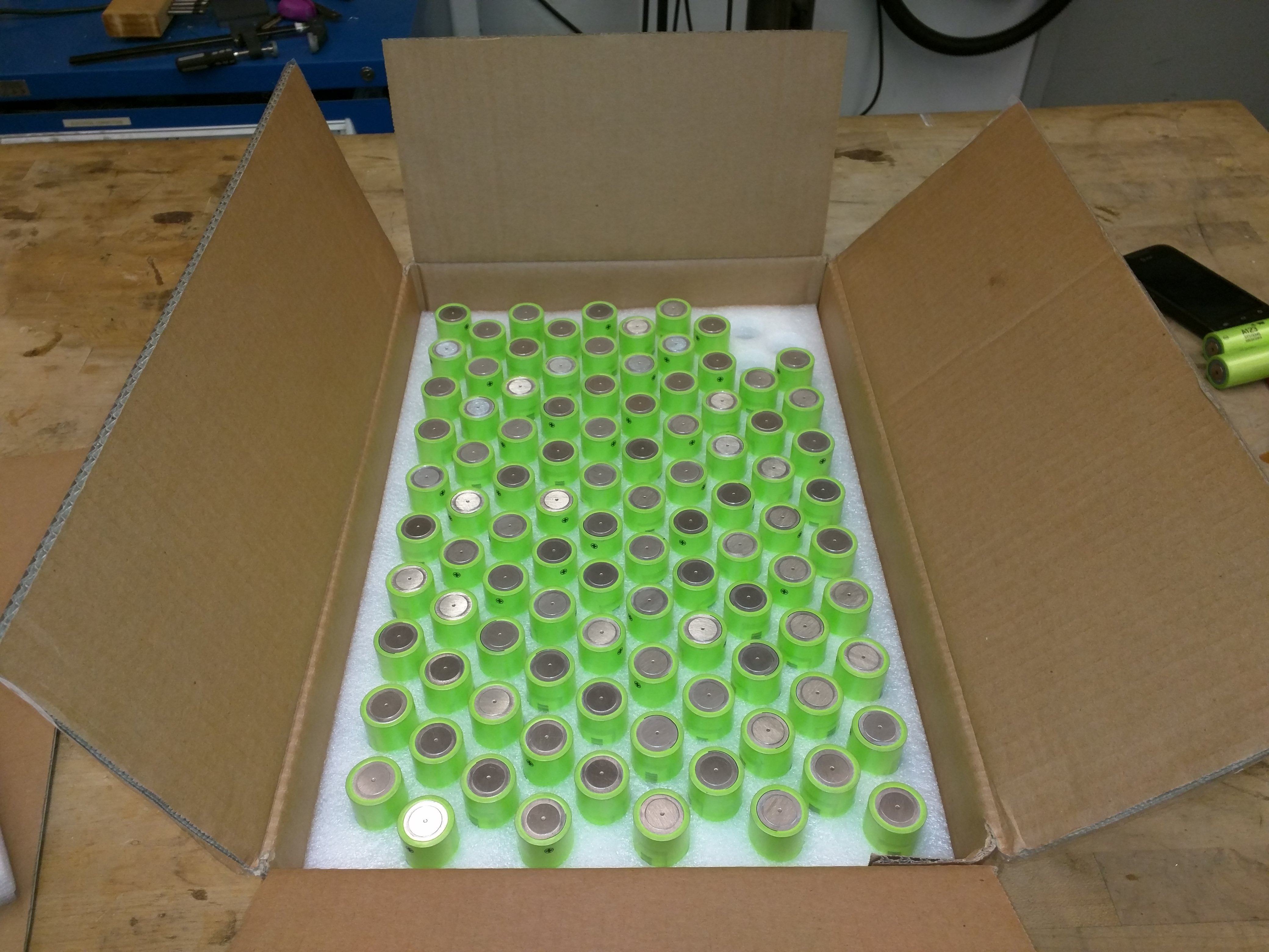
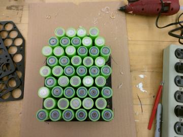
Time to make a new battery. My goal was three-fold, long-range, high charge rate and low cost. Fortunatley I was gifted ~100 brand new A123 26650 cells. These are 6mOhm 2.5AH cells, and with a bit of crafty modeling, they could fit inside the bohemoth and allow for some long range-scooting.

To fit in all these cells, I had a few options. Nominally welding the cells together with nickel tabs would be the best solution. Soldering directly to the cans is a tricky process and a good way to melt the internal cell seperators and create high internal discharge cells. I also had to sort out what to hold all these cells in place with. While I could have epoxy/hot-melt glued everything together, it would have been messy and limit the amount of heat the cells could reject. I chose to use Lasercut acrylic spacers to hold the cells apart. To do this I made two modules that were identical. As these are LiFe cells 16 cells is equivalent to a '~48v' system, this was convienient as it divided evenly into two seperate 8-cell modules.
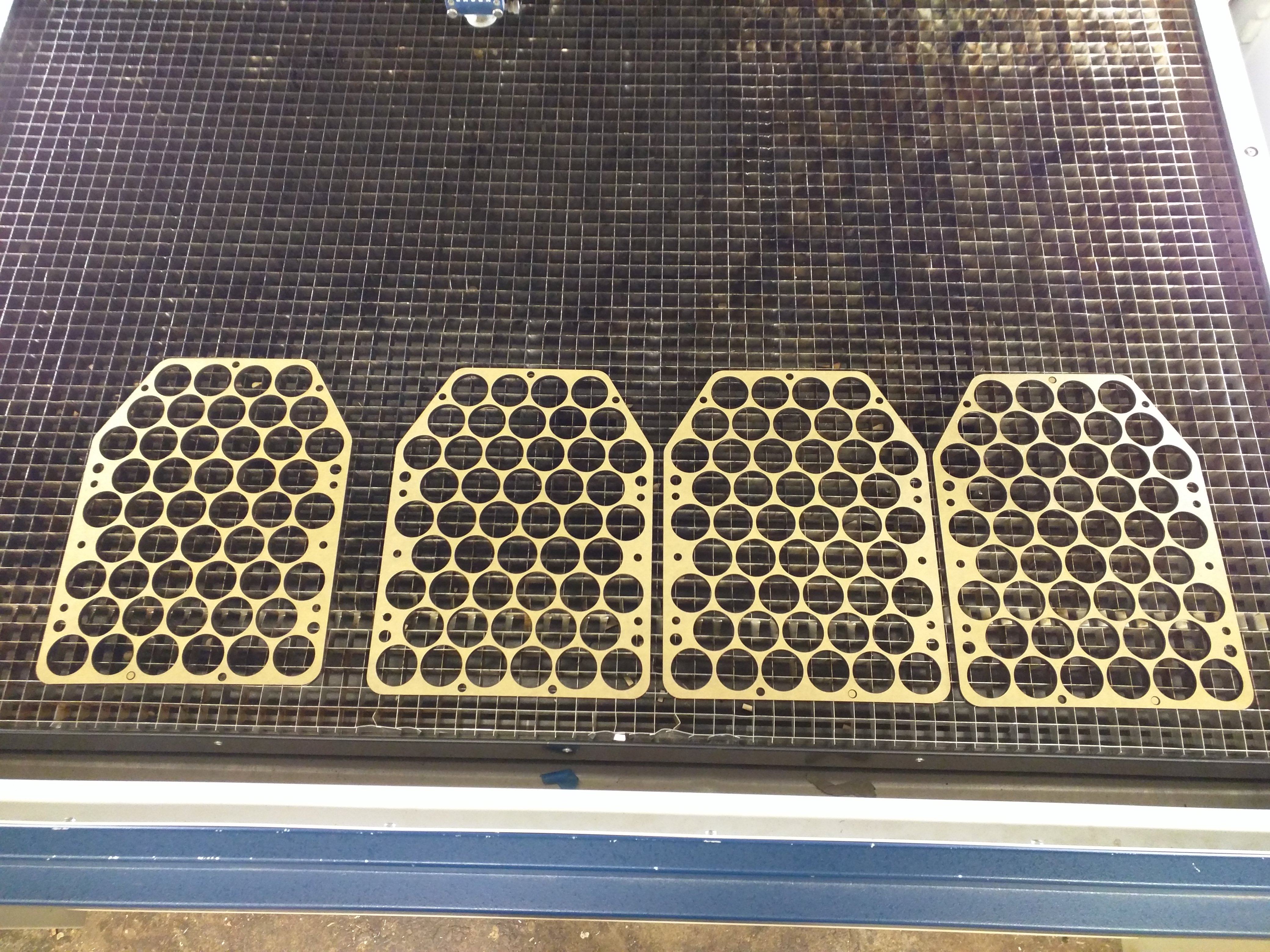
I did not personally have a laser-cutter, but was able to use a fairly nice 120w Epilog CO2 laser cutter over at the MIT Hobbyshop. This was my first go at laser-cutting, so i was a bit cautious. I wanted the cells to 'snugly' fit inside the seperators, and I was not sure what the Kerf or tolerances of the cutter were. I brought extra material to do a test cut of the diameter of the cell cutouts, and had a laptop nearby to edit the associated diameter in solidworks. I chose 1/4" thick acrylic (colored) as it was easy to cut on a laser-cutter, was relativley strong, and fairly low cost. These spacers should not normally see much mechanical stress.
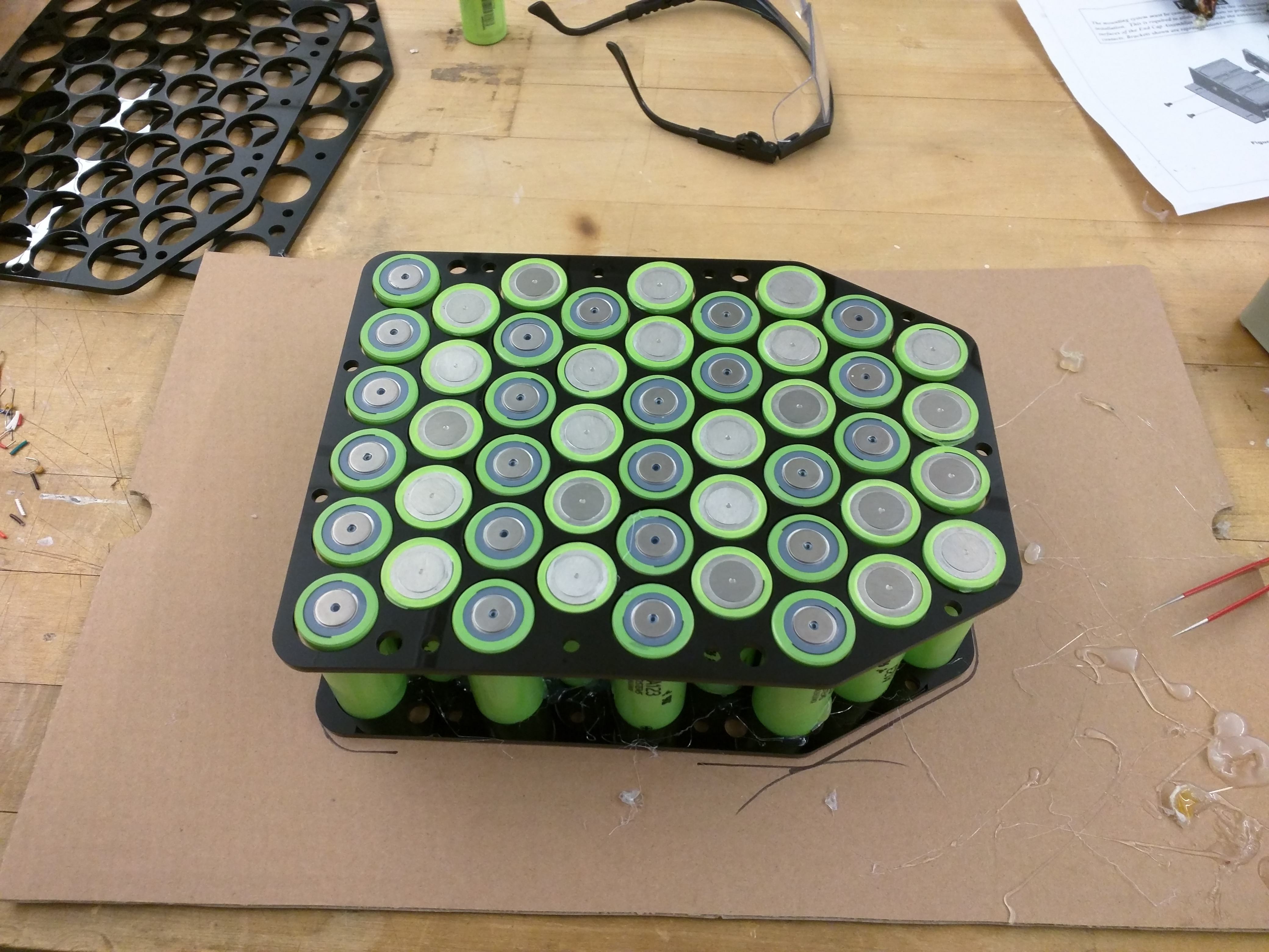
Like A Glove. The spacers fit wonderfuly, the 8S6P modules were coming together! Time to turn this pile of cells into a battery. The A123 cells are particularly weird, the CAN is a drawn aluminum and positive, with the smaller connection point (nickel-tin) negative. I was fortunate to find 26650 cell weld-tabs on Ebay. These are a nickel strip with an 'H' shape.

I decided to CAD up the entire battery module to get a better idea of how (2) packs would fit inside the inner cavity of the scooter. The design of the battery pack was kept as simple yet insulative as possible, all while being easy to assemble. My battery design is freely available through grabcad here.

Part III coming soon!
Want more? Here's a behind the scenes look at my workspace and some of the images that did not make the cut to be included in the write-up: